This is a new version of my balancing robot. Link to the old project: https://axelsdiy.brinkeby.se/?page_id=1141
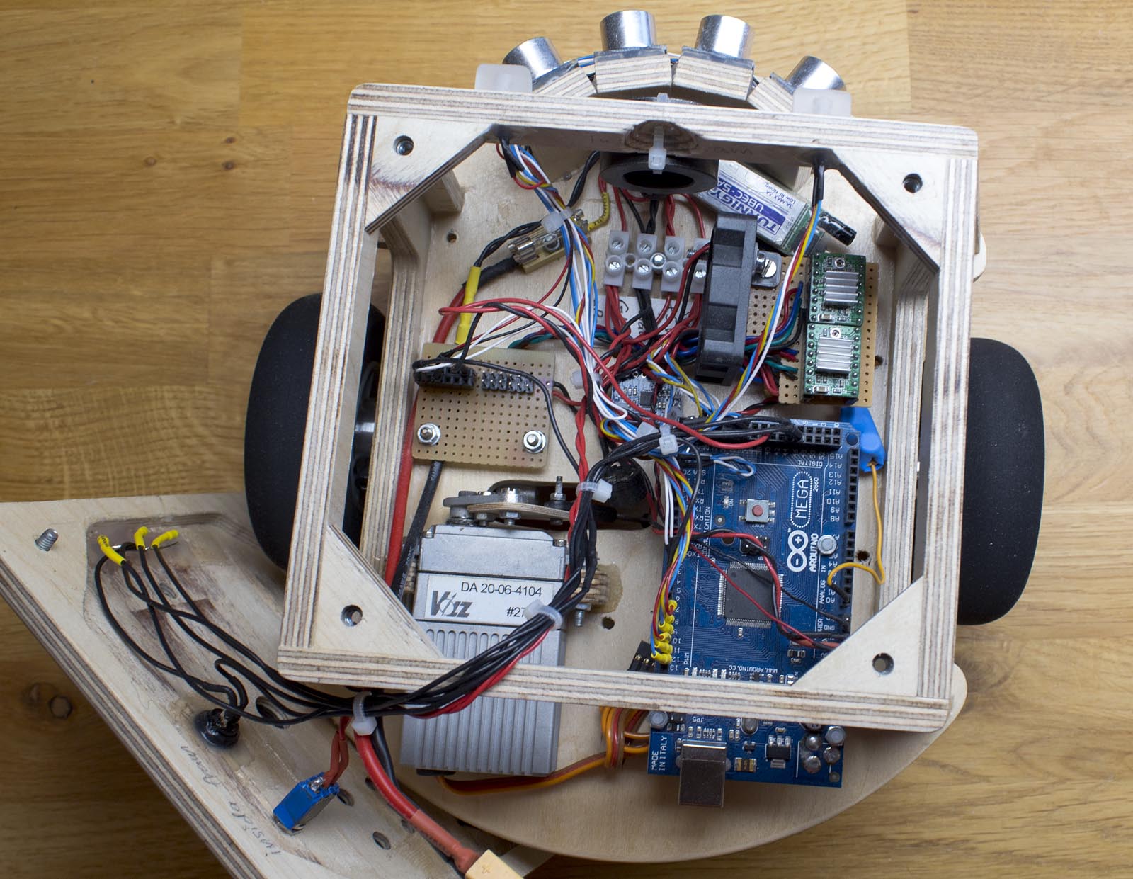
I have re-built the robot using a single Arduino Mega instead of my previous solution using three different Arduinos. I wanted to make a better more optimized solution. Schematic and source code is available.
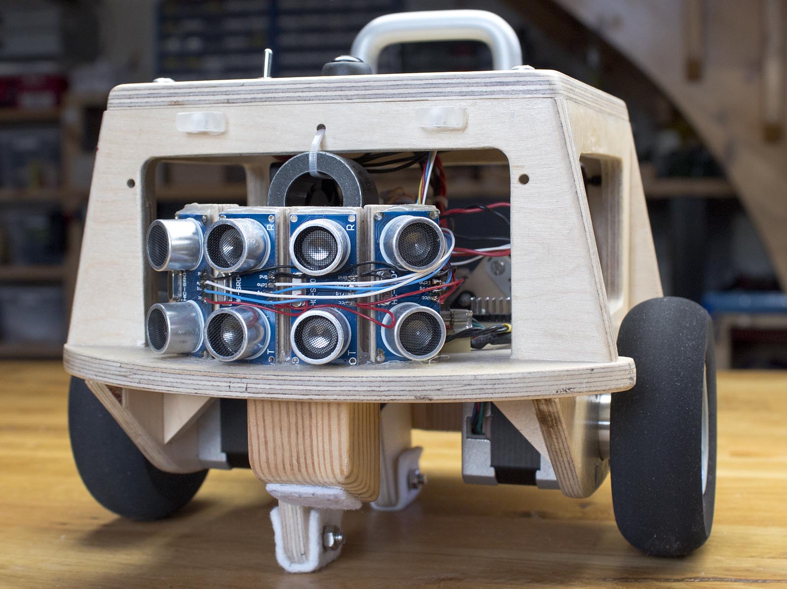
The robot is using the same NEMA 17 stepper motors and they are driven by hardware timer interrupts in the Arduino for smooth, precise and reliable operation. I am using regular A4988 stepper motor carriers of the same type commonly in 3D printers. Right now, the robot can use its four ultrasonic rangefinder sensors to run around autonomously and turn away from obstacles. One of the four ultrasonic rangefinder sensors is fired every main loop cycle, and the echo inputs from them are also handled by hardware interrupts.
The main loop is running at a variable speed, as fast as possible. The delta time (dt, the time it takes for the processor to complete one cycle of the main loop) is calculated in every loop cycle. The delta time is used when integrating the gyro signal, running the complementary filter and in the PID calculations. I have learned from my other balancing robots that it is important to have the loop speed as fast as possible to make the robot as stable as possible. This seems to be a better solution than using a fixed loop time.
An MPU-6050 IMU is used to get the angle of the robot. The Arduino reads raw data from the gyroscopes and accelerometers. The motion processing unit on the MPU-6050 is not used. The angle is estimated bu the Arduino by combining the integrated angle from the gyroscope with the angle calculated using accelerometer data. This is done using a simple complementary filter.
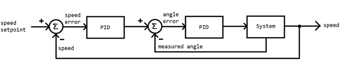
The balancing is done using the same PID cascade as my “mini balancing robot”. Link to that project: https://axelsdiy.brinkeby.se/?page_id=1447
The PID cascade is basically two connected PID controllers. One PID controller (the inner control loop) takes the difference between the desired angle and the current angle and calculates a speed for the motors. The second PID controller (the outer control loop) takes the difference between the motor speed and the setpoint speed as the input and calculates the desired angle.
This control system allows the robot to return to its original position when disturbed. The robot is also capable of finding a new setpoint angle for balancing if the center of gravity is moved, or the robot is standing on an inclined plane. Since I use stepper motors, no wheel encoders are needed for the feedback. The motors will always run at the speed they are commanded.
For example: If we want the robot to stand still, we can set the setpoint speed to 0. If the robot starts to drift forward (if the robot is front heavy, or if it is pushed) the I-part of the outer control loop will adjust the setpoint angle to lean back to try to get the speed to 0. This works because the integral of speed is position. The lean back angle will be proportional to the distance from the starting point. The P-part of the outer control loop makes the robot always lean slightly backward relative to its travel speed, this dampens oscillations otherwise caused by the I-part. Without the P-part the robot would go back and forth indefinitely and never come to a stop. No D-part is needed in the outer control loop.
When tuning this kind of system, I start with the inner control loop which calculates the motor speed based on the angle. I set the setpoint angle to 0 (straight up) and the I and D-gains to 0. Then increase the P-gain until I get oscillations. Then I slightly reduce the P-gain and add some I and D gain. When this is done correctly the robot should be able to balance, but it will drift away by itself, or when pushed. The robot should return to its straight-up angle relatively fast when pushed, and there should not be any high-speed oscillations, vibrations, or to large overshoot. After this, the outer control loop that controls the setpoint angle based on the speed can be tuned. This is usually much easier, just add some P and I gains and experiment.
This robot also has a stand that is operated by a servo. My intention is to make it so that the robot can lift itself up and start to balance on its own again if it falls over. But this is not yet implemented in the code. I would also like to add a remote control mode in the future.
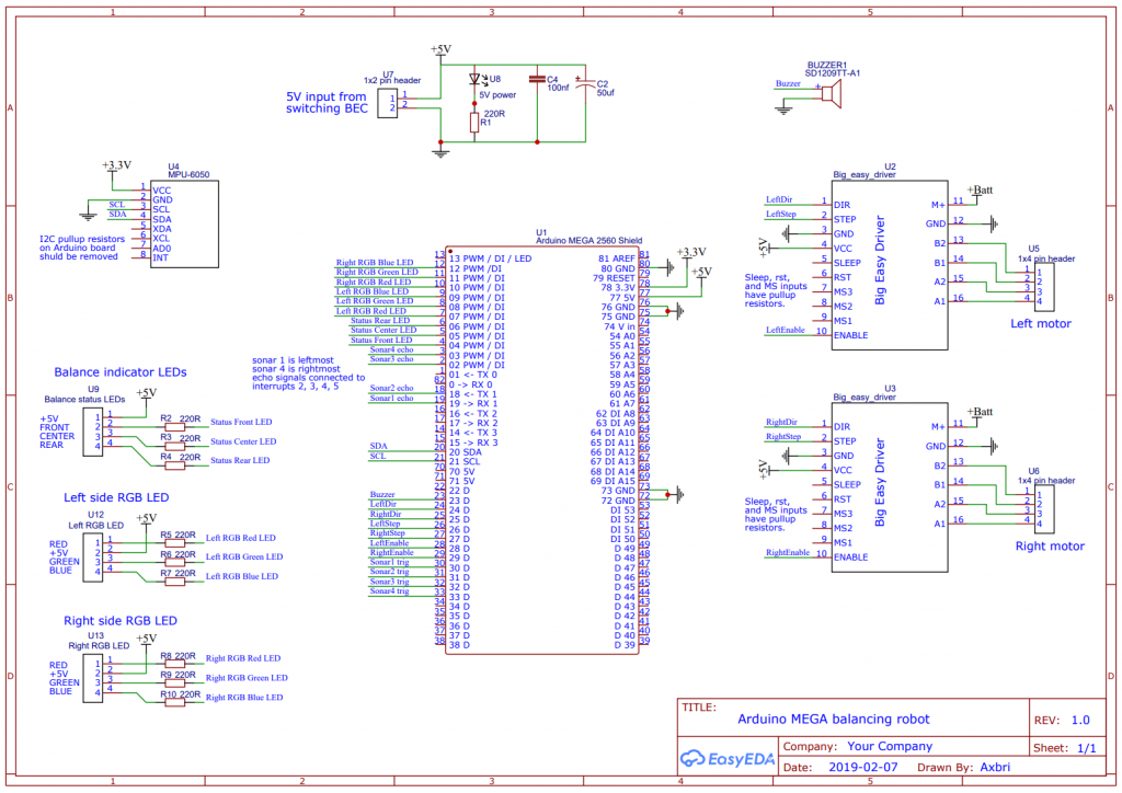
Link to EasyEDA project with schematic: https://easyeda.com/Axbri/arduino-meg…
Link the download my Arduino code: http://brinkeby.se/downloads/MegaBalancingRobotV1.zip