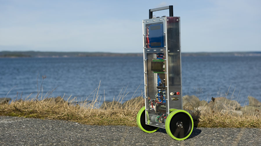
EquipoiseBot is my first two wheeled self balancing robot. It can be controlled using a homebuilt IR remote. This is my fourth robot built in the fall and winter of 2011 – 2012.

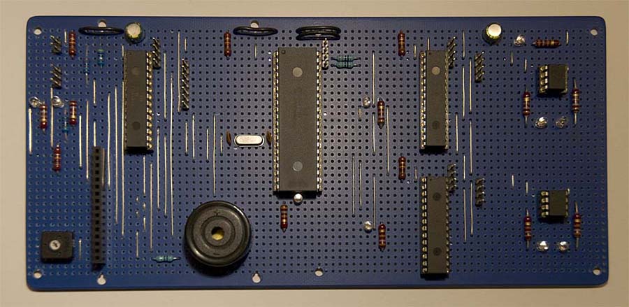
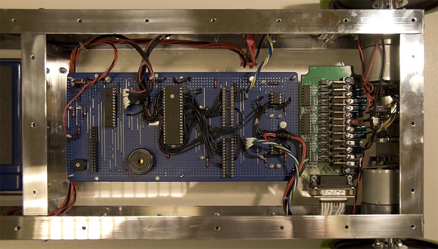
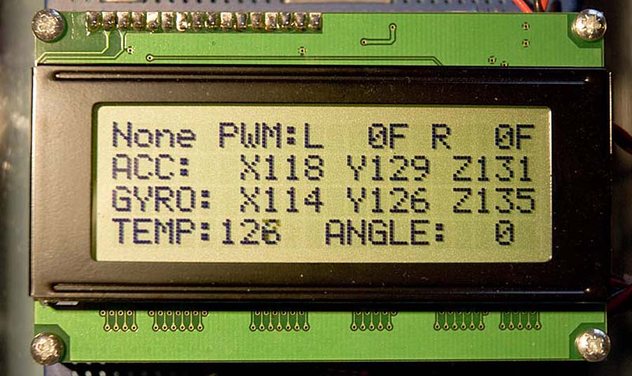
The robot uses two accelerometers and one gyro to make it balance. Two different values representing the angle of the robot are calculated. One from the accelerometers using the mathematical tangent-function and one from the gyro using integration. Those two angle values have different pros and cons. The angle signal from the accelerometers is very noisy, but this is an absolute value of the angle relative to Earth’s gravity. The signal from the gyro is less noisy but it has drift problems.
The two angle values are combined in a filter to make one new value that is both accurate and absolute, relative to Earth’s gravity. This new angle is used as input in a PID regulator to control the motors, keeping the robot in balance.
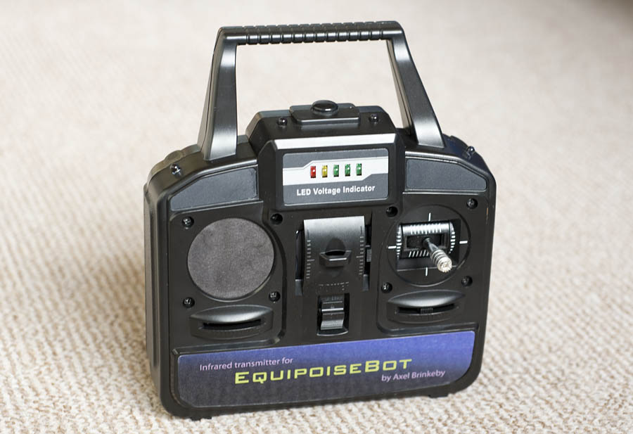
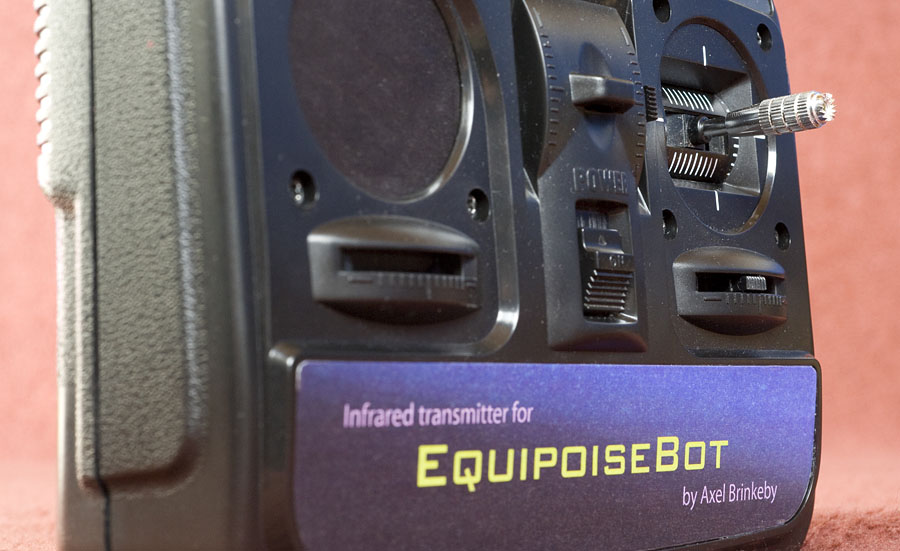
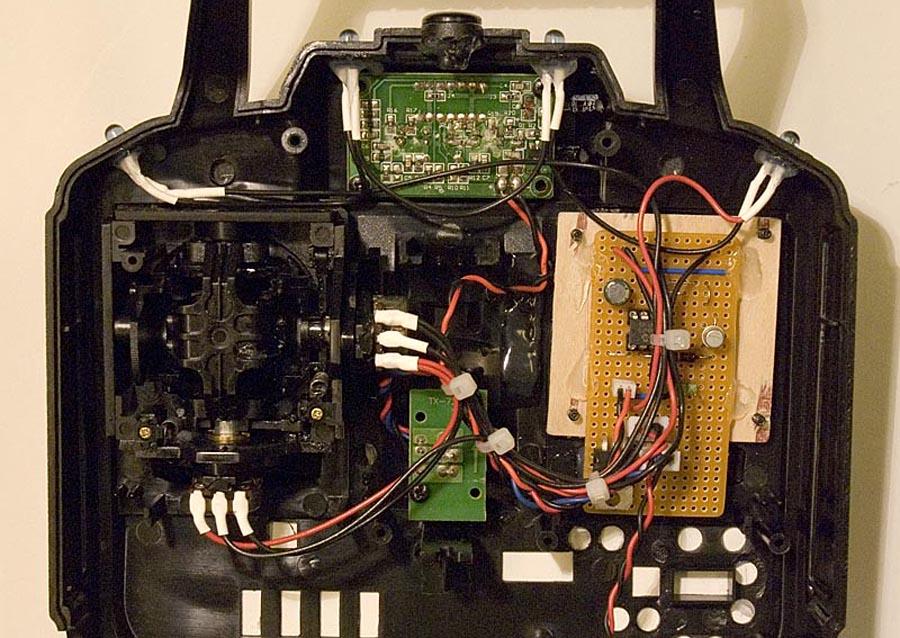
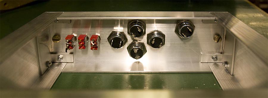
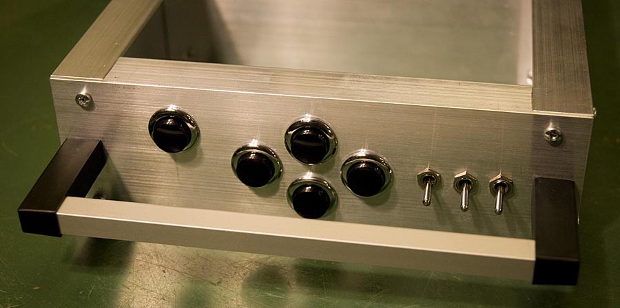
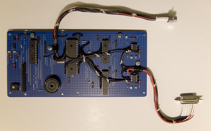
The remote is built in the casing of an old transmitter from an RC helicopter. The transmitter sends the X and Y positions of the control stick over IR using standard 1200 baud serial data modulated with 38KHz and a simple homemade data protocol.
The steering signal from the remote is just added to one of the motor signals and subtracted from the other. The forward/reverse signal from the remote is added to the angle value after the filter described above. The steering works great but the forward/reverse is far from perfect. The remote is commanding the robot to lean at an angle, not to drive at a commanded speed. Also, there is nothing that prevents the robot from driving too fast, if this occurs the robot falls over. This makes the robot a little bit hard to control.
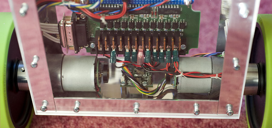
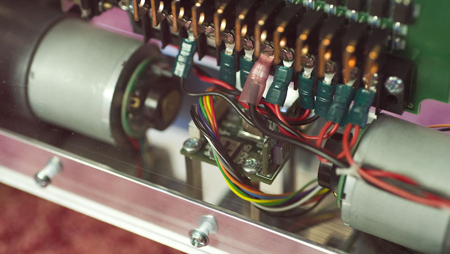
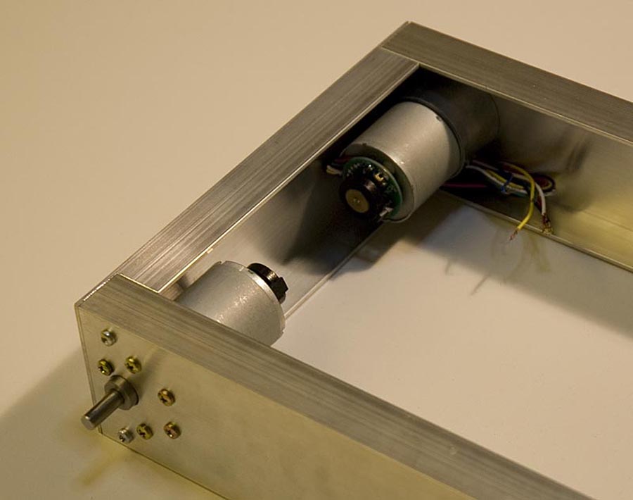
EquipoiseBot is equipped with quadrature wheel encoders. Those are not used at all, but in the future, they can be used to make the robot stand still in one place or to improve the remote control function.
Update 2017-09-20
Download the SketchUp-file here: EquipoiseBot_SketchUp.zip (5MB).
Hello Axel,
Some years ago I contacted you about the EquipoiseBot. Since then I am experimenting too with balancing robots.
I have read many sites about this subject, but I still can’t manage the robot to balance in a stable way. I can send you
some video about this, if you want to see it. When changing the PID parameters in many ways, it still shakes slightly.
Not how it should operate properly, but it manages to balance. I used Xbee Wifi modules to change those parameters
wirelessly. The offset angle or tilt angle to balance this robot is also problem. The center of gravity is not perfectly located above the wheels axis , so the robot needs a little tilt angle to keep the balance.
Now I am making a new balancing robot with stepper motors. And I have found a site
and also the ARDUINO GITHUB SOFTWARE for making this robot. I am going to make it like this Manolo example using bluetooth communication. Another example, I have read, is from . Both Manolo and B-Robot use a double PID-controller. This seems to solve the problem with the tilt angle, caused by the CG.
My first robot lacks the cascading PID controller and uses brushed motors without encoders. Well one thing is for sure. I love experimenting
with balancing robots and I want to make one day a good one. By the way I am very impressed by your new “Balancing robot with Raspberry Pi” also with stepper motors. Stepper motors are more precise and I have found out that brushed motors have always differences in speedvariations.
I have also a question for you, Axel. What is the best way to configure the cascading PID controller? There is little information about
this to find on any sites I have mentioned above. Any useful information is welcome for me and my new project. What is the best way
to approach this configuration.
Also have a look on my own first website . Still “work in progress” with new projects coming soon.
With kind regards,
Sjaak van der Zande
To make a good balancing robot that can compensate for CG changes etc. two cascaded PID regulators are needed. The “Equipoise Bot” does not use this method but the “Balancing robot with Raspberry Pi” does. The idéa is that one PID regulator controls the speed of the wheels depending on the differance between the robot’s angle and a setpoint-angle. Then another PID regulator controls controls this setpoint-angle based on the difference between the robot’s speed and a setpoint speed. If you want the robot to stand stil, this setpoint-speed is 0. The robot’s speed is the output of the first PID regulator if the robot uses stepper motors, or encoder speed data if the robot uses DC motors. You start by tuning the first angle-PID until the robot can stand upright and then tune the speed-PID. I will keep an eye on your website 🙂
Hello Axel,
Thanks for your reply about the explanation of configuring the parameters of the cascading PIDs. First the angle-PID and then the speed-PID. I will keep that in mind. Your design “Balancing robot with Raspberry Pi” is very nice and practical. Do you have maybe a converted PDF file of your mechanical design to construct the balancing robot myself? Your design-files I have downloaded, but I don’t have SketchUp. Please give me some design format to work with. Freecad is my kind of 3D designing program.
With kind regards,
Sjaak van der Zande
Hi Axel,
I have downloaded SketupViewer to view your design.
I could print it to 1:1 scale, but I needed to cut and paste it in the old fashion way
(scissors and scotch tape) to have the demensions of your design.
In FREECAD I will make a 3D model for futher use and get the seperate parts to print it out
on paper to make my Balancing Robot. Maybe I will print some 3D-parts with PLA to make this robot.
Bye Sjaak
Hi. I usually copy and paste the parts of a SketchUp model I want to print in a separate file, and use the built in printing functions in SketchUp to make a tile-print in scale 1:1. And yes, I also cut the papers to size manually and tape them together. You can probably save a lot of work if you have a 3D printer 🙂
Hi. I have not done a PDF for any of my robots, but SketchUp Make is free, you can download it to view and print my design. I think you can export parts of the 3D model to a PDF using SketchUp if you want. I have never tried Freecad, but it looks interesting. Maybe I should try using that program on some other design in the future.
Hi!
Do you share your code and design? Is it possible to download it anywhere?
Thanks and Regards
Armin
I am not very satisfied with the code or electronics solution in this robot, therefore I will not share it. But a have updated the page and added an old SketchUp file with contains all mechanical parts. Its made in an old version of SketchUp, but you should be able to open in current versions of the program.