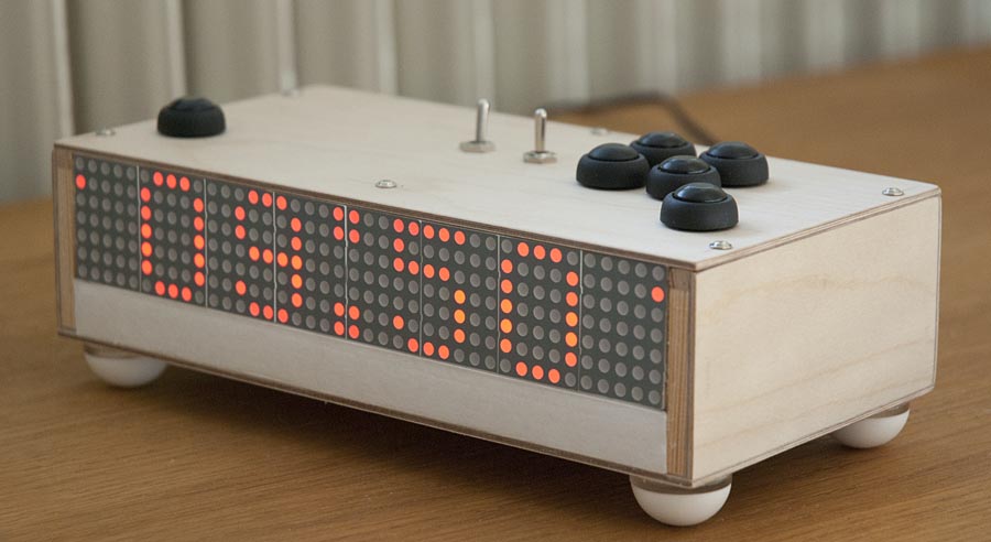
This is my homebuilt alarm clock. It has a lot of extra features that are not available on alarm clocks you can buy. I built it because I wanted to learn more about Arduino by making something bigger than just basic getting-started projects on a breadboard. Previously all my electronics projects involving micro controllers have bin based on PIC processors, which I found very different from working with Arduino.
Features of the alarm clock:
- Time is synced using GPS, no need to set it manually, only time-zone setting is necessary.
- internal real time clock module ensures the clock still works in case of bad GPS signal.
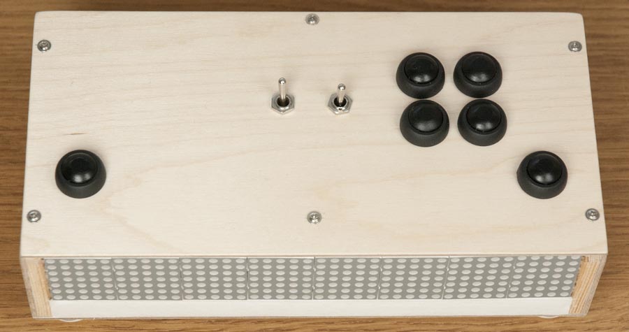
- An easy-to-use multi-button interface to set alarm time.
- Alarm time and time zone setting is stored in EE-PROM memory in case of power failure.
- Real audio amplifier and speaker system, not just a “buzzer”.
- All sound effects are stored as files on an SD-card.
- 4 external programmable 12V power outputs for bedside lights etc.
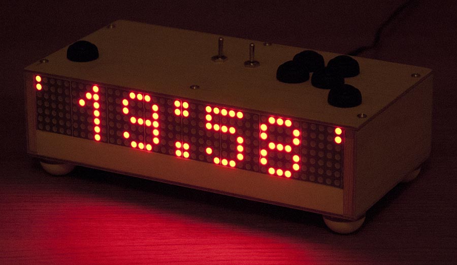
The clock is controlled mainly from a real time clock module. It keeps track of time and date, and it runs in 24h mode since that is what we use in Sweden. The time and date is set every three seconds using a GPS, if there is a valid position FIX. This way, the clock is extremely accurate and still completely “maintenance free”.
The clock uses a orange 7×40 LED dot matrix display. The numbers on the display are big. And since it is a dot matrix display, it is possible to display any numbers or letters at any positions. I think this is a large advantage compared to normal 7-segment numerical displays. I never considered using a LCD display since I find them hard to read in low light conditions. LED displays also have 180 degree viewing angle which no LCD can match. the columns of the display are controlled directly by pins on the Arduino. The rows are controlled using IPS031 power switches. This means that 40+7=47 pins are needed to control the display. The Arduino then displays one row of the display at a time. Some sort of display driver chip could probably have been used, but i wanted to keep things simple and use as little external components as possible.
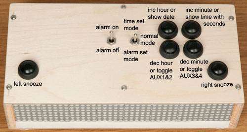
The clock has three modes: “Time set mode”, “Alarm set mode” and “Normal mode”. This is controlled by a three position switch. Four pushbuttons is used for making settings. In Time set mode, only the time-zone (hour setting) can bee changed. One button increments it, and one decrements it. There is no need to set minutes or date since that is handled by the GPS. In alarm set mode, one button increments minutes, one decrements minutes, one increments hours and the forth decrements hours. Both hours and minutes are programmed to “wrap around”. If you have 23 hours and increments you get 0 hours. In normal mode the current time is shown. Here the pushbuttons toggles AUX outputs or shows current date when pushed. The AUX outputs provides 12V power. The idea with this is that you can connect a 12V light that will automatically switch on in the morning when the alarm goes of. The alarm can easily be switched on and off using a two position switch. If the alarm is switched on, animated indicators are shown on the sides of the display.
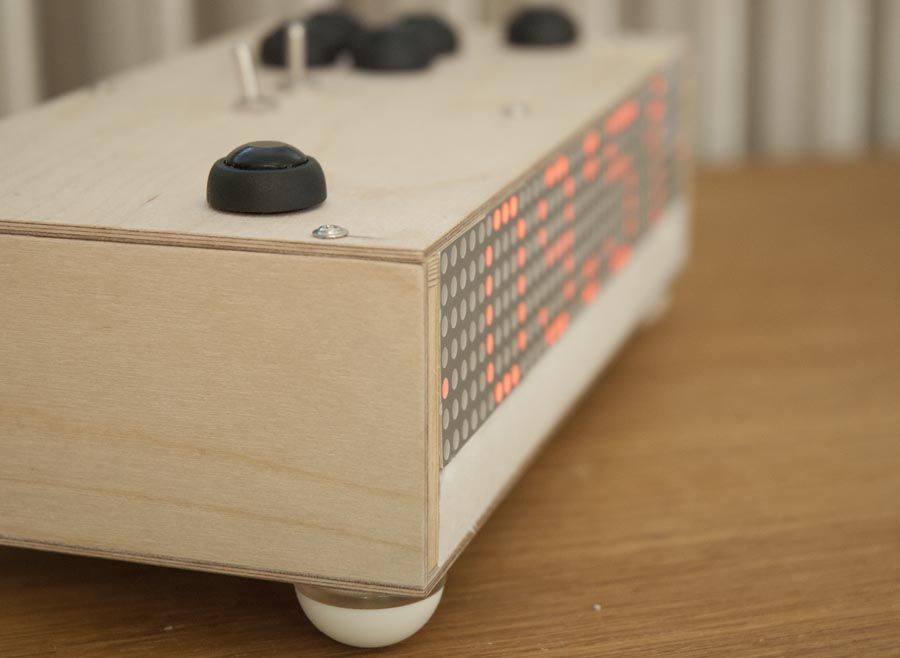
When the alarm goes of, it is stopped by pressing any of the two pushbuttons on the top front left or right edges. Then the clock enters snooze mode. It will sound the alarm again exactly nine minutes after it was stopped the first time. To exit snooze mode. Both the left and right snooze-buttons needs to be pressed simultaneously. This prevents snooze mode from being exited accidentally. During snooze, one of a few calm, low volume, snooze-music tracks are played. This is a feature I have not seen before in any alarm clock, and I really like this feature!
List of components I have used:
- China copy of Arduino Mega 2560 R3 .
- DS3231 real time clock module
- Wtv020sd16p audio playback module.
- SMART-KIT-1040 audio amplifier
- Turningy 6V 3A switching power supply
- BTS133 Power switches to control power to AUX outputs and audio system.
- GPS from a OSD-system for RC aircraft, but any NMEA GPS will work.
- LITEON LTP1457AE 5×7 LED dot matrix display
Circuit diagram: (click on the image to show full size)

Download all project files (182 MB) (includes Arduino code, SketchUp model, circuit diagram, some images, and all audio files on the SD card)
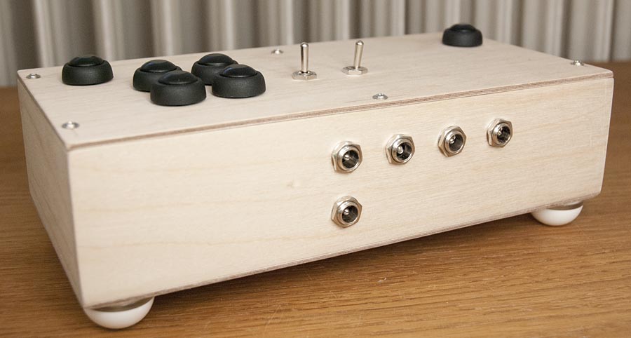
Power input and the four AUX power outputs on the back side.
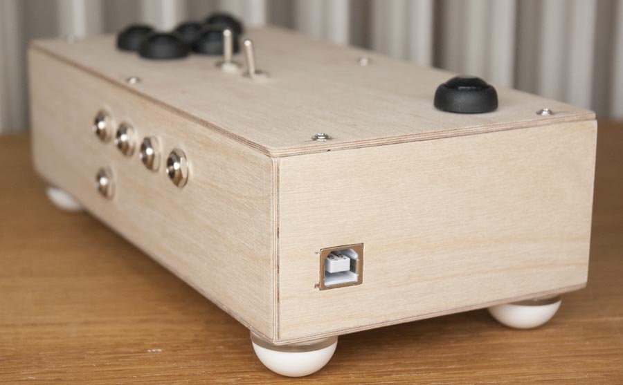
The USB port on the Arduino is available on the outside for easy software updates.
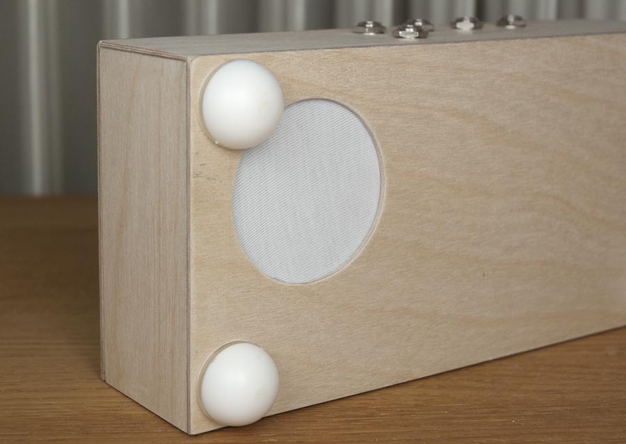
The speaker is located on the bottom.
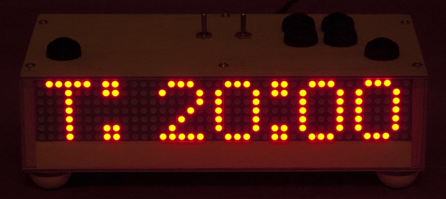
Time set mode: Current time is shown on the display. The time-zone (hour) setting can be adjusted with the pushbuttons.
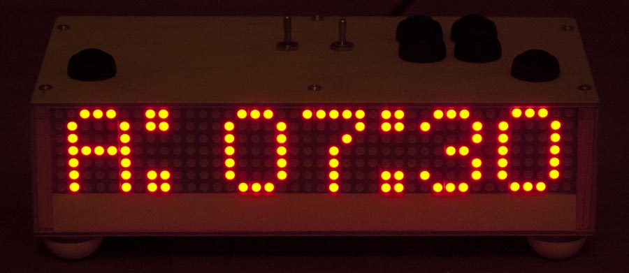
Alarm set mode: The alarm time is shown on the display. The alarm time can be adjusted using the pushbuttons.
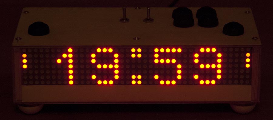
Normal mode: The animated alarm indicators on the sides of the display shows that the alarm is currently activated.
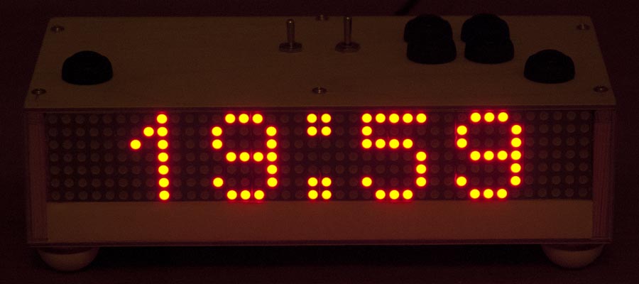
Normal mode: On animated alarm indicators on the sides of the display. The alarm is off.
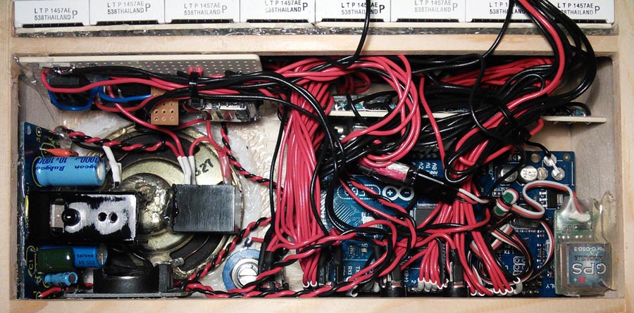
The inside. not mush space left here. Maybe I should have made the box a bit bigger…
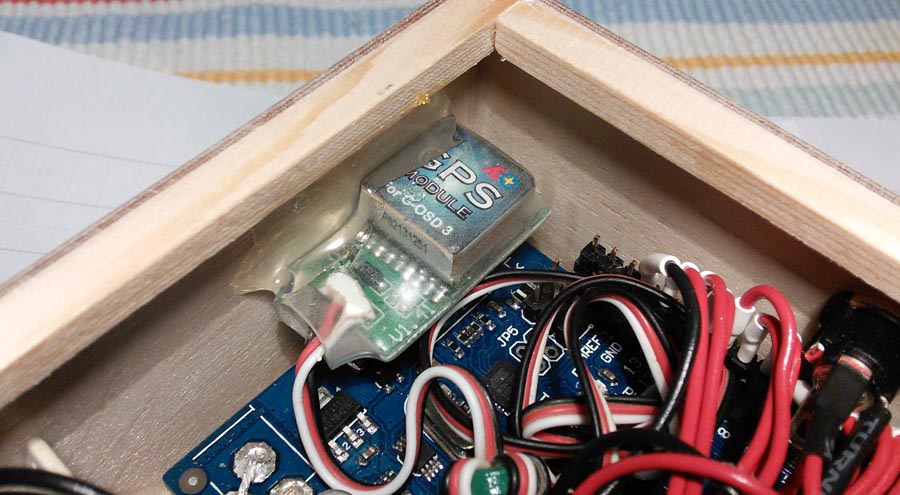
GPS module.
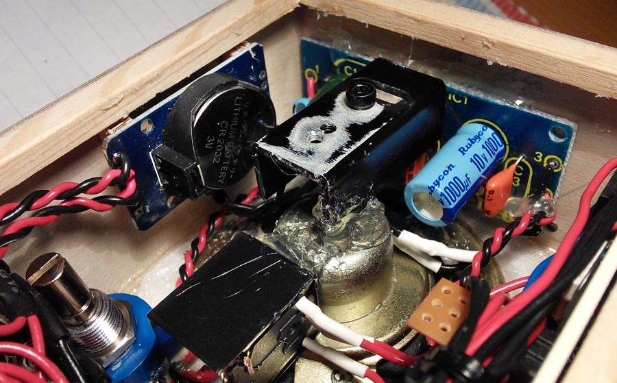
Real time clock module and audio amplifier. The potentiometer controls the volume. The relay controls power to the audio system. Power is switched of to prevent unnecessary power consumption and heat distribution when the audio is not used.
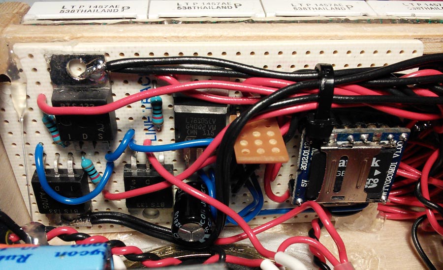
Power switches for audio system and AUX outputs on the left. Audio playback module with SD card on the right. The audio module has its own 3.3V power regulator to prevent noise from reaching the speaker.
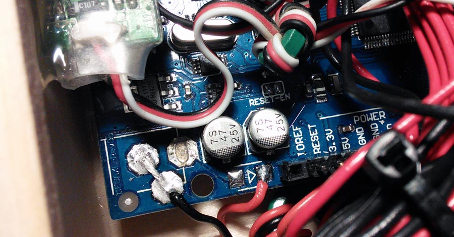
The Arduino has a reversed polarity protection diode on the power input. I have removed it, this allows it to work on only 6V instead of 7V as they recommend. I have also removed the power jack and soldered the cables directly.
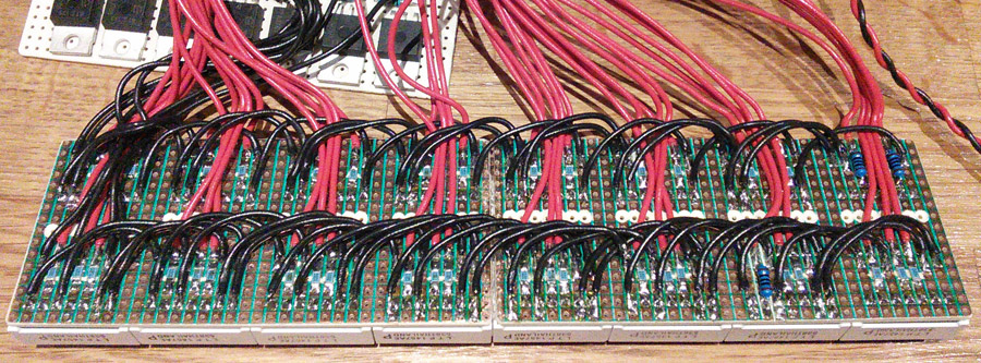
The display was probably one of the most time consuming parts of all soldering work, but is was very rewarding when it worked for the first time.