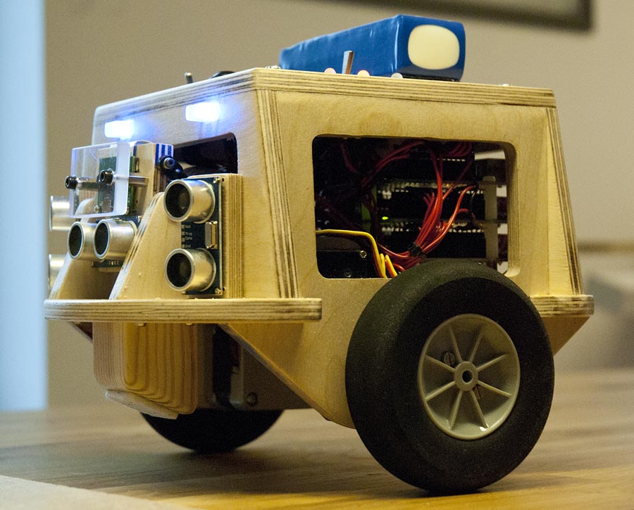
This is a two wheeled self balancing robot designed to look interesting, and at the same time work as a platform for experimenting with more advanced things than my other robots where capable of. This robot is based around multiple Arduinos and one Raspberry Pi.
Power
This robot is powered by a 3 cell 2200 mAh LiPo battery, the same type as a use in some of my model airplanes. This battery provides around 12 volts. This voltage is supplied to all the arduinos. They regulate there own 5 V to power the connected peripherals. A 5 V switching regulator is used to power the Raspberry Pi and is’t peripherals such as the WiFi dongle and the camera. The Battery voltage is monitored by one of the Arduinos, the robot stops balancing if the voltage falls to low.

Electrical System
The Arduinos will do low level functionality like as balancing, controlling motors and getting data from sensors. The Raspberry Pi Will do higher level functionality such as remote control, obstacle avoidance, navigation and maybe image processing.
The are four Arduinos. One main controller runs the balancing code, this one also talks to the Raspberry Pi over a serial connection. Then there is one Arduino controlling the three ultrasonic distance sensors and the tilt servo for the camera. Lastly there is one Arduino controlling each stepper motor. All Arduino boards communicate with each other over I2C (Arduino wire library). The 6 DOF IMU used to estimate the angle of the robot is also connected on this I2C BUS. The main Arduino is “Master” and all the others are “Slaves”.
Balancing
The robot uses a MPU_6050 6 DOF IMU mounted on a breakout board. This is a three axis accelerometer and three axis gyro. Only one gyro and two accelerometers are used. The angle of the robot relative to the earths gravity is calculated using the math arctan function. This angle is the merged together with the angle rate from the gyro to make the reading more solid.
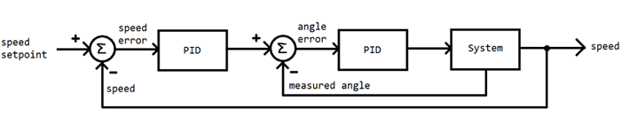
To keep the robot in balance, a PID cascade is used. One PID regulator adjusts the speed of the motors to maintain a setpoint angle. The other PID regulator adjusts this setpoint angle according to a setpoint speed. This control system allows the robot to return to its original position when disturbed. The robot is also capable of finding a new setpoint angle for balancing if the center of gravity is moved, or the robot is standing on an inclined plane. The main Arduino in the robot reads sensor data, estimates the angle of the robot, and runs this control system about 150 times per second.
High level control
The balancing system described above makes it easy to control the robot to move backwards, forward and make it stand perfectly still by just setting the setpoint speed for the PID cascade. To make the robot turn I just add some speed to one wheel and remove exactly the same speed from the other wheel. This way, the overall forward/backward speed is not changed when the robot turns.
Stepper motor speed control
The robot uses two NEMA 17 stepper motors connected directly to the wheels without transmission. The motors are controlled by two “Big Easy Driver” boards. They have potentiometers to control the current to the motors. They also allow for different micro stepping modes, including One sixteenth steps, either Step, quarter step, half step and full step modes.
One Arduino is used to control each motor. The Arduinos receive speed values over I2C from the main controller. The time in microseconds between steps are calculated based on the desired speed. One sixteenth steps are used at low speeds. Since the stepper motors have 200 steps per revolution this gives 3200 steps per revolution of the wheels, which is more than enough to make small adjustment to keep the robot in balance while standing still. At higher speeds, the Stepping mode is switched either eighth step, quarter step or half step mode depending on the speed. The ensures that the step-time does not get to small. This is done because is seams like the Arduinos are not very accurate with timing short delays.
Sensors
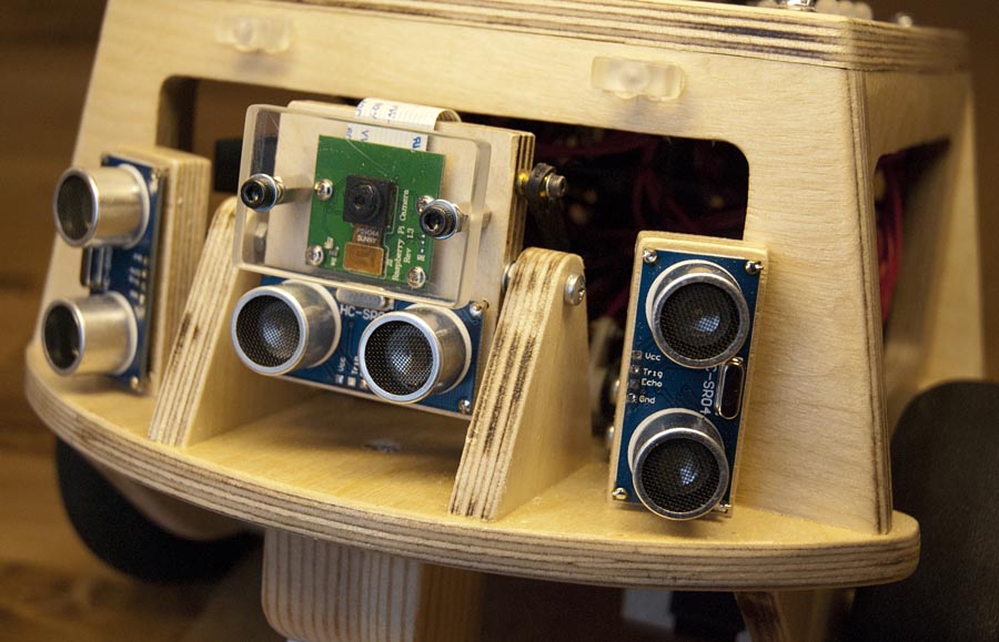
The robot is equipped with three ultrasonic distance sensors as well as the Raspberry Pi camera module. The Camera together with one distance sensor is mounted on a plate that can be tilted up and down by a servo. The other distance sensors are mounted on ether side, pointed slightly outwards to the sides. The distance sensors are fired of in sequence to prevent interference.
My intention is to use the three distance sensors for obstacle avoidance, to prevent the robot from running into stuff. The center distance sensor can also the used to measure the distance to any flat object the camera may be looking at. It is possible to access the distance sensor’s values with centimeter precision. The have a range from 2-3 centimeters to about 1.5 meters.
Raspberry Pi
A Raspberry Pi 2 model B is used. I use a USB to WiFi dongle connected to the raspberry Pi that allows it to access the internet. This allows me a log into the command interface using SSH and transfer files using FTP.
In the future a may also experiment with remote control from a phone app, or even a website on the internet. My intention is also to try some basic image recognition using the Raspberry Pi camera. I think it is possible to follow a colored object, or even line following. The main reason the camera is mounted on a tilting plate is to make it possible to follow objects up and down. There is no need for panning since the robot can easily rotate around it’s on axis while standing still.
Mechanical construction
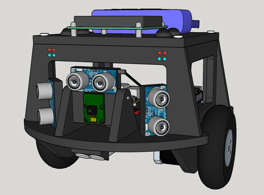
The main chassis is made out of 8 mm thick plywood. It was first designed in SketchUp, then all the wooden parts were printed in scale 1:1 and glued onto to wood for sawing. The SketchUp file is available here: http://brinkeby.se/downloads/BalancingRobotWithRaspberryPi.zip(12MB)

All the pieces was glued together with wood glue, and then sanded. The top part of the chassis is mounted with four screws that allows it to be removed to access the electronics mounted underneath. All wooden parts are covered in a few coats of clear varnish for protection.
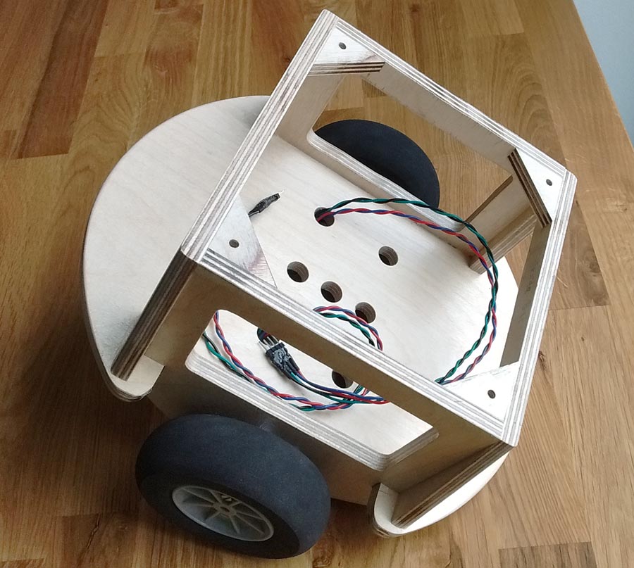
The wheels used are 95 mm model airplane wheels. The wheels are mounted on the stepper motors using custom lathed aluminium wheel hubs. The hubs are secured to the motor axes using large stop screws.

The underside of the chassis has plenty of ground clearance. There are two stops that prevents the robot from leaning more than about 25 degrees in ether way. This prevents the robot from falling over complacently. This also protects the floor from damage.
