This is my attempt at building a really good indoor obstacle avoidance robot. The main goal of this project was to create a robot that can drive around by itself in a normal indoor environment and not get stuck. In the future I want this robot to be able to dock in a charging station and charge itself. I also wanted this robot to be a platform for experimentation and demonstration of different robotics techniques.

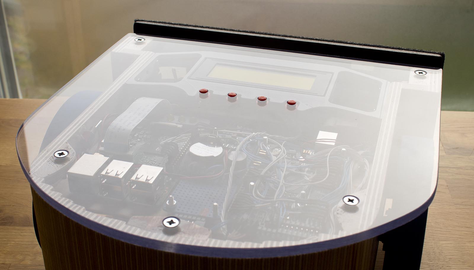
The main chassis of the robot is built out of 9 mm thick plywood. The top is made out of acrylic. Some 3D-printed parts are used to mount the different components. A lot of thought has been put into the design and shape of the robot. I wanted the robot to be relatively easy to build using simple tools. I wanted it to be round to minimize the risk of it getting stuck, and I wanted a chassis that could be maneuvered with high precision, while at the same time being able to drive over small obstacles like cables or doorsteps.
I settled on a design with two large drive wheels and a rear caster. The rear part of the chassis has the shape of a half circle. When the wheels of the robot are driven in opposite directions, the robot spins around the center of this circle. A flat bumper covers the entire front of the robot. This way, if the robot hits something, the bumper is guaranteed to get triggered. The weight of the robot is around 3.5 kg. The majority of this weight is supported by the two drive wheels. The weight of the rear caster is only about 0.3 kg. The robot is 25 cm wide, 26 cm long, and 14cm high. The diameter of the main wheels is 12.3 cm. The ground clearance is about 3 cm, but the bottom edge of the front bumper is about 2.5 cm above the ground. If the robot encounters an obstacle it cannot go over, the bumper will ensure it turns around instead.
The weight of the robot is around 3.5 kg. The majority of this weight is supported by the two large 12.3 cm diameter drive wheels. The weight of the rear caster is only about 0.3 kg. The robot is 25 cm wide, 26 cm long, and 14cm high. The ground clearance is about 3 cm, but the bottom edge of the front bumper is about 2.5 cm above the ground. If the robot encounters an obstacle it cannot go over, the bumper will ensure it turns around instead.


A 20×4 character LCD and four pushbuttons act as a user interface. The user can start and stop the robot, monitor values from all the sensors as well as change some values, like PID settings for the motors. The user can also enable and disable different features like sensors, PID control of motors, etc. The display also shows the battery voltage and charging status.
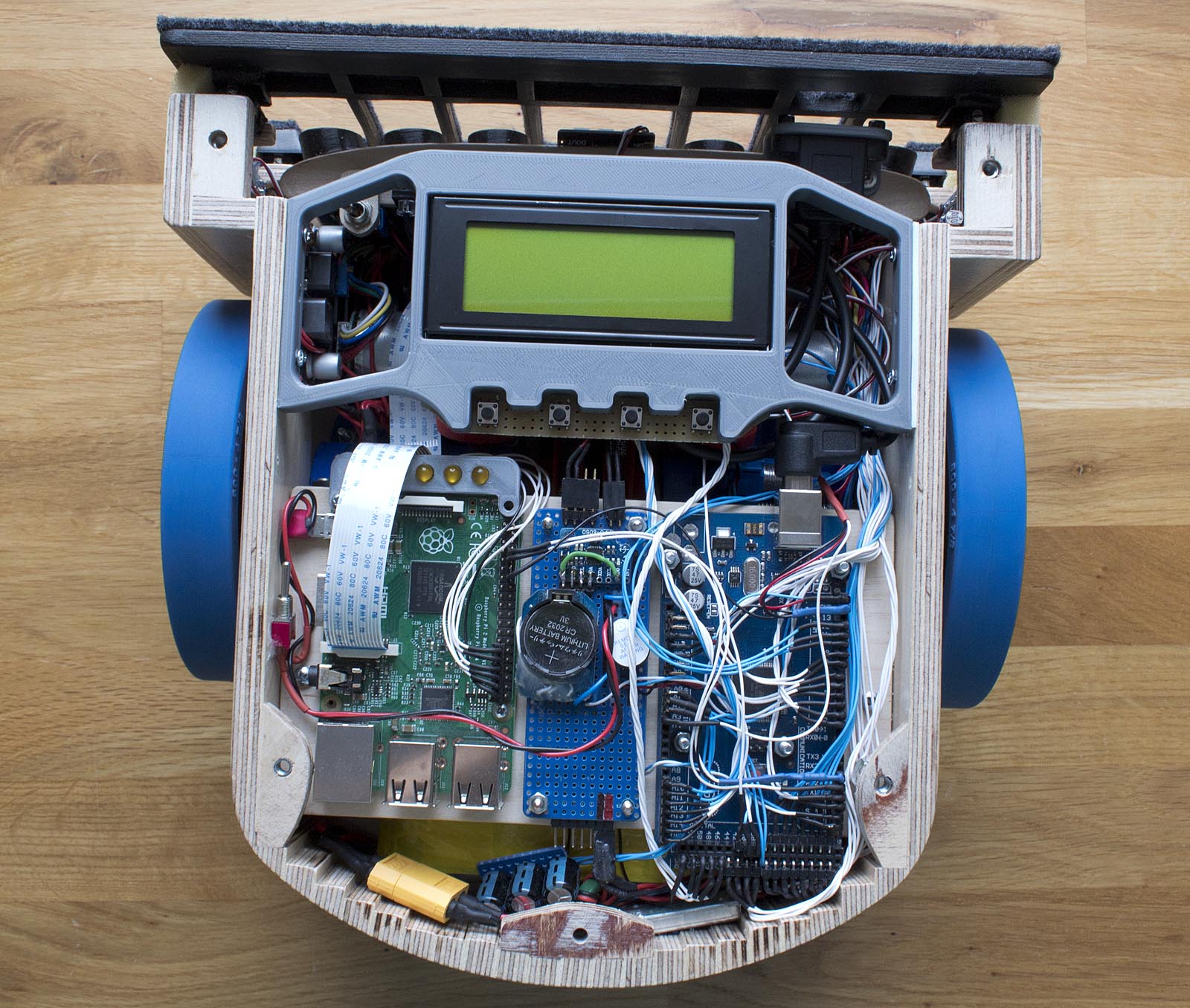
The main processor of this robot is an Arduino Mega 2560. It reads all the sensors and runs its main loop a 100Hz, controlling the robot. There is also a Raspberry Pi with a wide-angle lens camera module in the robot. This is mainly for experimenting with computer vision in the future. It can communicate with Arduino using serial. As can be seen in the images, I have also connected a couple of LEDs directly to the GPIO pins on the Raspberry Pi which can be used for debugging.

Two geared DC motors with quadrature encoders are used. The gear ratio of the motor gearboxes is 1:30. Then the motor shafts are connected to the wheel shafts using GT2 belts and 3D printed pulleys with a gear ratio of 1:4, resulting in a total gear ratio of 1:120. The belts are tensioned using springs and can slip if the torque on the wheels gets too big.
The quadrature encoders of the motors give 48 pulses per motor revolution, resulting in 5760 pulses per wheel revolution. This is obviously very high resolution, and this is perfect for controlling the speed of the robot using closed-loop PID control or counting “ticks” while doing precise maneuvering of the robot.

An old 2000mAh 12 Cell NiMH battery is used to power the robot. The battery lasts about 2-3 hours while driving around avoiding obstacles, with the Raspberry Pi turned off. My main reason for choosing a NiMH battery instead of a lithium battery for this project was safety reasons, and it is easy to build a charger for NiMH batteries. The robot has a custom built-in constant current charger that can slowly and safely charge the battery unattended. Since there is a voltage drop over the LM317 voltage regulator, used as a constant current source, the charging current will drop as the voltage of the battery increases. I am not sure if this is the best way to build a NiMh charging circuit, but this seam to work in my case at least.
Since there is a voltage drop over the LM317 voltage regulator used as a constant current source, the charging current will drop as the voltage of the battery increases. And since the charging current is very low, the battery will not get damaged if charging power is left connected for several days. Since the charging circuit is not controlled by the Arduino at all, the robot can be charged while switched off. And if it is switched on while charging, the Arduino can monitor the input voltage to determine if the robot is charging or not. I am not sure if this is the best way to build a NiMh charging circuit, but this seam to work in my case at least.

Link to EasyEDA schematic of the battery charge circuit here.

A 5V switching power regulator (BEC module intended for RC models) is used to provide 5V power for all electronics, including the Arduino, all the sensors, and the Raspberry Pi.

An L298N Dual H Bridge is used to drive the DC motors. The Arduino controls the dual H-bridge using its PWM pins. I have adjusted the PWM frequency in the Arduino to 4000Hz by setting the prescaler to 2. This gives the least irritating switching sound from the motors. I have tried higher PWM frequencies, but it makes the L298N run less efficiently, causing it to overheat.
The main sensors used for obstacle avoidance are eight HC-SR04 sonar sensors. The robot also has a front bumper with mechanical keyboard switches (cherry MX blue) in the corners for collision detection. I use mechanical keyboard switches since they are robust, and rated for many presses. The soft foam close to the switches increases the force needed to activate them, preventing false triggers.

The 3D-printed plastic cylinders around the sonar sensors prevent the sensors from getting triggered by the front bumper. The USB type B connector that can be seen in the image is an extension of the USB port on the Arduino Maeg 2560, allowing me to upload new code, without removing the top acrylic plate.
There is also an LDR (light-dependent resistor) connected together with a regular resistor, acting as an ambient light sensor is used to activate the LED light next to the Raspberry Pi camera while it is dark, illuminating the camera picture.
The robot also has an MPU6050 3-axis accelerometer/gyro. This is not currently used, but it can be used in the future for wheel slippage detection while making turns, or to detect if the robot is lifted or if it is tilting in any direction.
The robot has a real-time clock module. My intention with this in the future, is I get self-charging to work. The robot can leave the charging station at specific times or days in the week.
Computer vision
As mentioned above, the robot is equipped with a Raspberry Pi and a wide-angle camera module. One of the things I have tried experimenting with is sign reading. Making the robot react and perform different pre-programmed maneuvers when it is detecting different signs. This is done using OpenCV and a Python script.


The Python script works like this. Firstly an image is captured by the camera module. Then, some gaussian blur is applied to remove small details and contours. After that, a canny edge detector is used to filter out all high-contrast edges in the image.

The OpenCV function findContours() is now used to find contours in the image. After this, the function approxPolyDP() is used to approximate the polygons of the contours. I am looking for a polygon with four corner points that has an area that is larger than a set threshold value. If a polygon that fulfills those requirements is found, I assume that it is a valid sign. If the corner points of this polygon are plotted on top of the original image, it looks like this:
After the four corner points are found, the points need to be sorted in a known order. In my case, I sort the points so that the first point is the top left one, the second point is the top right, the third point is the bottom right and the fourth point is the bottom left. When the ordering of the point is known the OpenCV function getPerspectiveTransform() can be used to get a transformation matrix from the original image to a new image of a given size, in my case, 256×256 pixels. Then the function warpPerspective() is used to apply the transformation and “dewarp” the perspective in the image. The result from this looks like this:

Now a threshold image can be created from this image with the OpenCV function threshold(). Now it looks like this:

This image can now be compared against images stored on the Raspberry Pi. For example: if I want to compare those two images:

I can subtract the stored images from the generated threshold image, pixel by pixel.

And then, it is just a matter of counting the number of white pixels in the images. If the number of white pixels is lower than a given threshold value, I interpret that as a match. The index of the matching image is then sent over serial to the Arduino, controlling the robot.
I will probably experiment and add more computer vision features in the future.
Download
In this downloadable folder, I have included the complete design of the robot, made in SketchUp. Some 3D prints were designed in Autodesk Inventor, and the design files for those parts, as well as STL files, are also included. No code is available yet, as I am still working on this robot. I will probably add both Arduino code and Raspberry Pi computer vision code here in the future.
Future development
In the future, I will continue to experiment with:
- Use the camera and computer vision for some sort of navigation or detecting and reacting to stuff.
- Self-charging: getting the robot to find a charging station and dock with it, probably using computer vision.
- Implement some sort of low-power standby mode, that could be used while charging. Make it possible for the Arduino to start and shut down the Raspberry Pi.
- Improve obstacle avoidance behavior even more. Implement a proper state-machine and use more sensors and smarter algorithms.