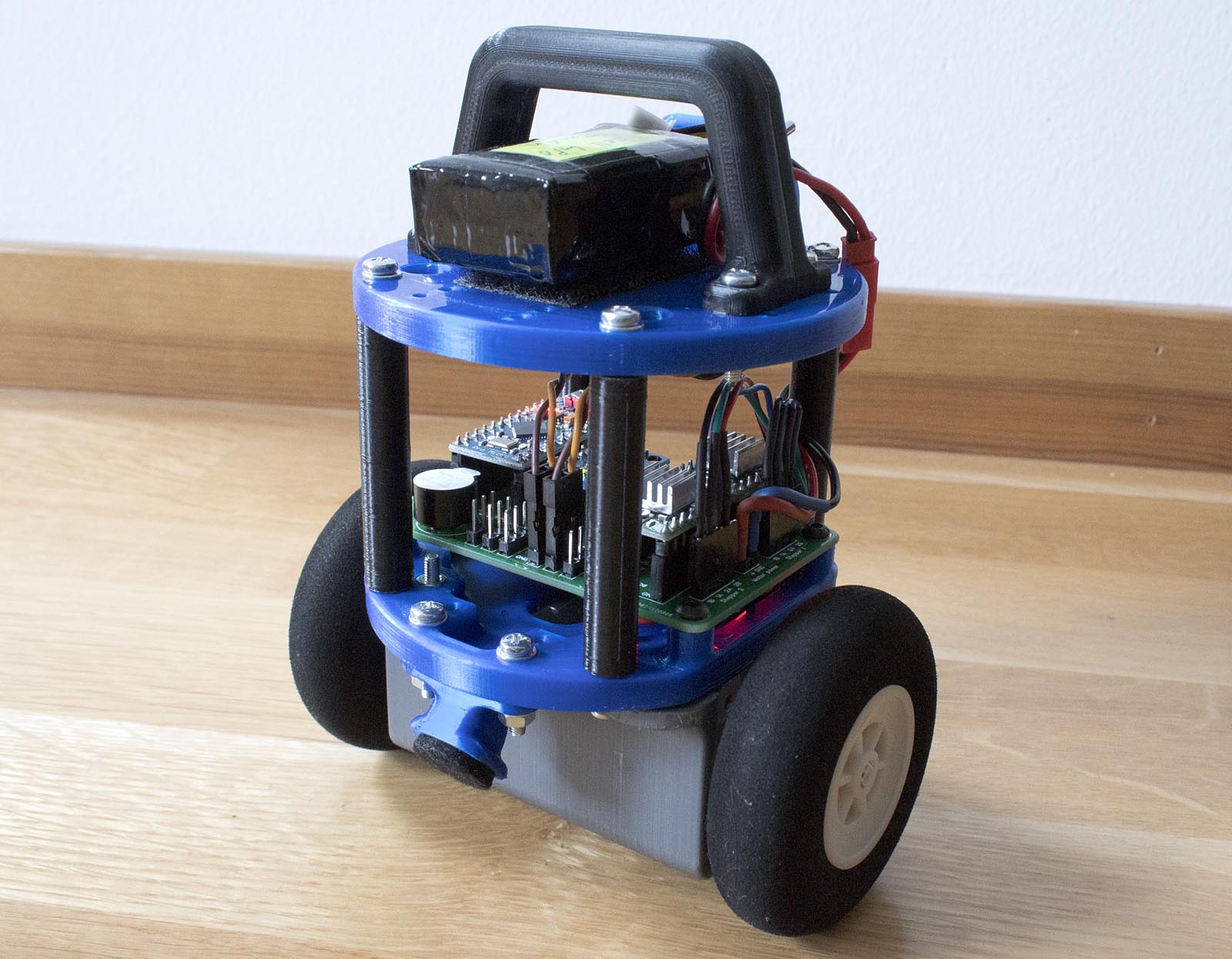
This is my version of a small self-balancing robot. A have tried to keep the design as simple and cheap as possible, without compromising performance. The robot uses two NEMA14 stepper motors and the electronics consists of a single Arduino Pro Micro and a MPU-6050 gyro/accelerometer breakout board. Two A4988 stepper drivers are used to drive the motors. The mechanical construction of the entire robot is made up of several 3D printed parts that are screwed together with M3 screws, this makes it fast and easy to assemble.
I provide the code, schematic and STL-files in a download at the bottom of this page.
Part list
Here is a port list including the most important components needed to build this (or a similar) self balancing robot:
- Arduino Pro Micro (clone)
- 2 pcs. NEMA 14 stepper motors (1.8 degrees per step)
- 2 pcs. model airplane wheels, the hubs are drilled up from 4 mm to 5mm and press-fitted onto the motor shafts
- 2 pcs. A4988 Stepper motor driver modules
- MPU-6050 gyro/accelerometer breakout board
- 3 cell LiPo battery
- A buzzer, an LED, and a few resistors. (check the schematic in the downloadable folder)
- A few pin headers and sockets, some wire, and some heat shrink tubing
- About 20 pcs. M3 16 mm screws with nuts are used to assemble the robot
- Two toggle switches used for auxiliary functions

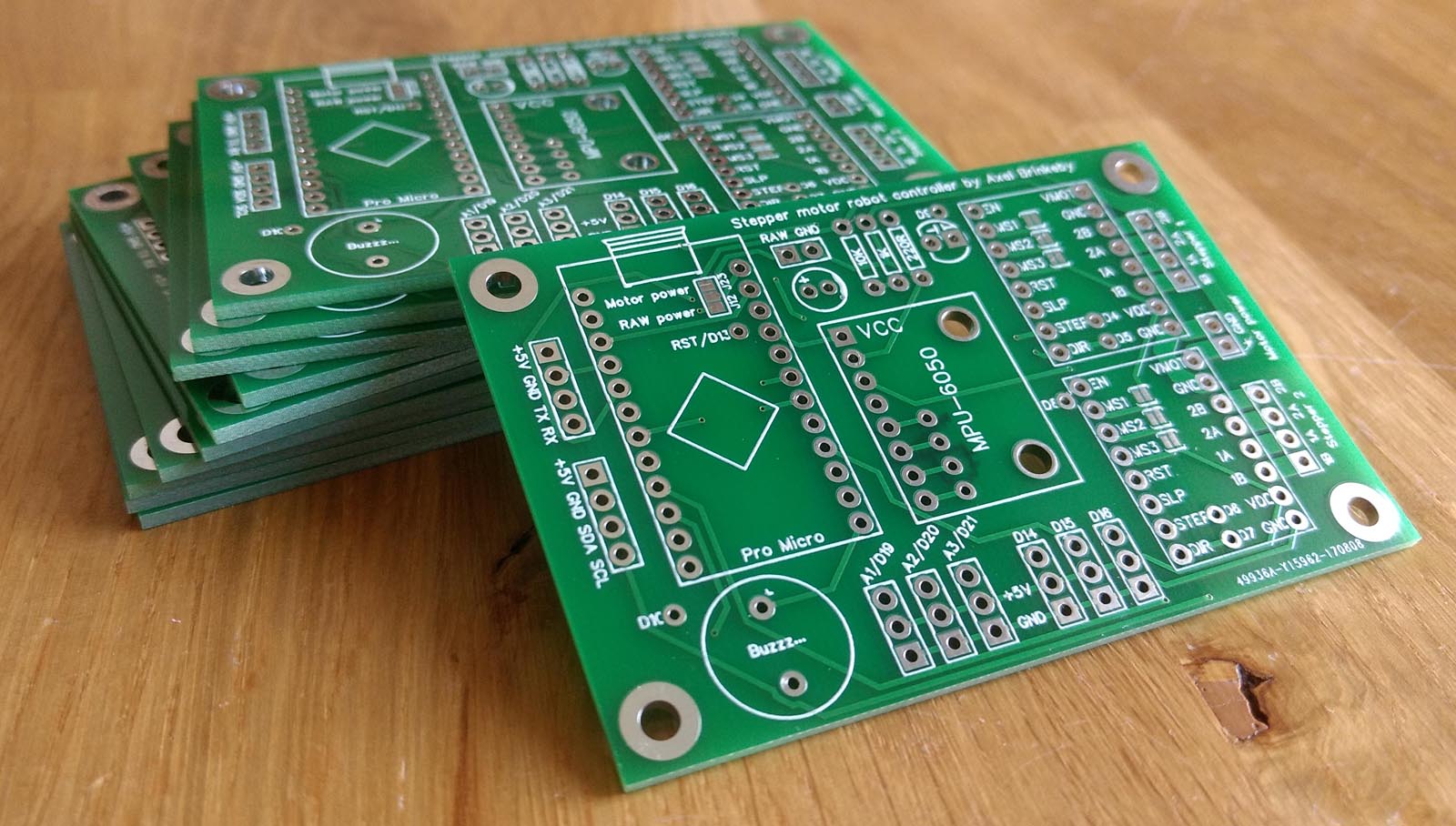
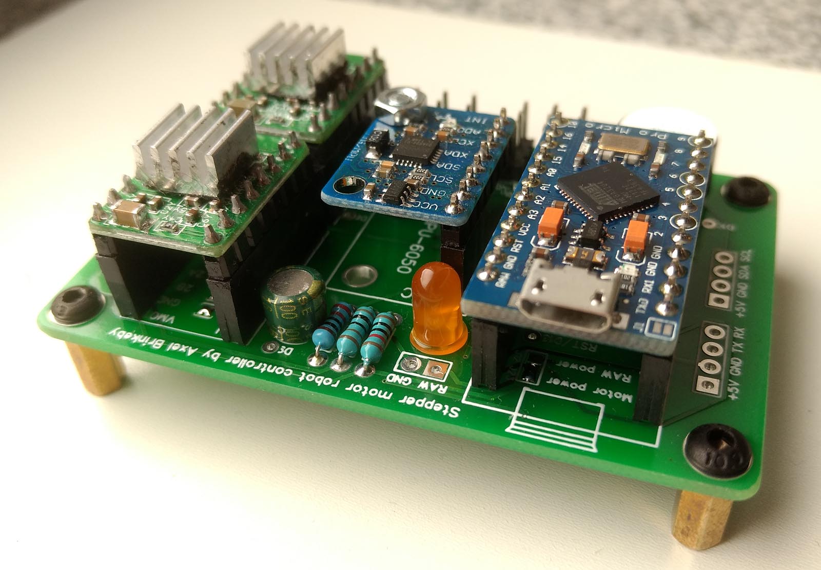
PCB design and electronics
This robot was also the first time a tried to design and order a custom PCB. I ordered it from EasyEDA, and I also used their browser-based design software. I am very pleased with the quality of the PCBs from EasyEDA, and the price is amazingly low. I will probably use EasyEDA to make more PCBs in future projects.
Using a custom PCB in this case, was probably a bit unnecessary because there are very few components, and I almost entirely use breakout-boards. But it was still an interesting challenge to design a PCB for the first time.
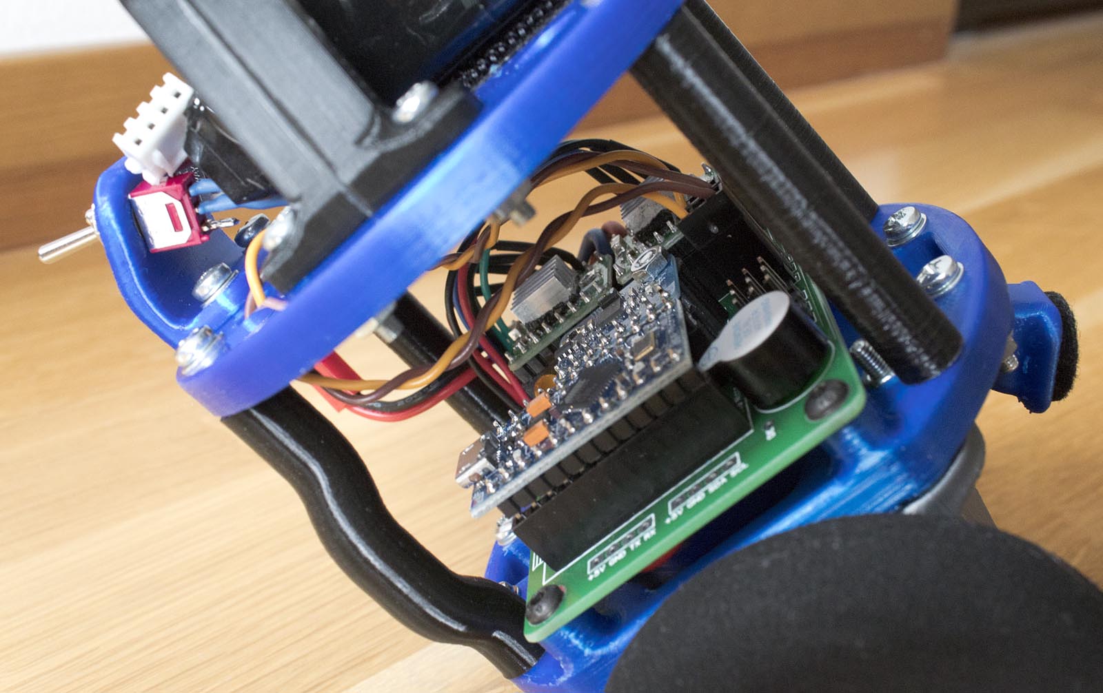
Note 1: I power the Arduino Pro Micro and other electronics using a switching 5V BEC module. The input of the BEC is connected to the motor input on the PCB, and the output of the BEC is connected to the “RAW” connector on the PCB. I have selected “RAW power” on the solder jumper on under the Arduino. The Arduino can be bowered with higher voltages than 5 volts, it has its own onboard voltage regulator. But I have found that it can get quite hot when powered from the battery directly, which is almost 12 volts.
Note 2: I run the stepper motor drivers in 1/16 micro-stepping mode. This means I have connected all the solder jumpers under them.
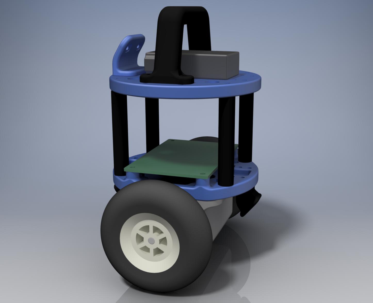
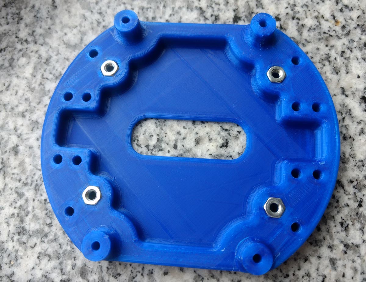
Mechanical CAD
I have designed all the mechanical parts for 3D printing is Autodesk Inventor. I know that not many people have access to this software, but I have still included the source files, as well as the STL-files in the downloadable folder at the bottom of this page.
The design consists of two round plates that are held together with spacers. The stepper motors are clamped in place with a bracket. The are many pairs of holes 20 mm apart that can be used to mount various extra parts to the robot. I have created a mount for two switches, and a handle, as well as tip-over stops. This makes it easy to add more things, like obstacle sensors in the future.
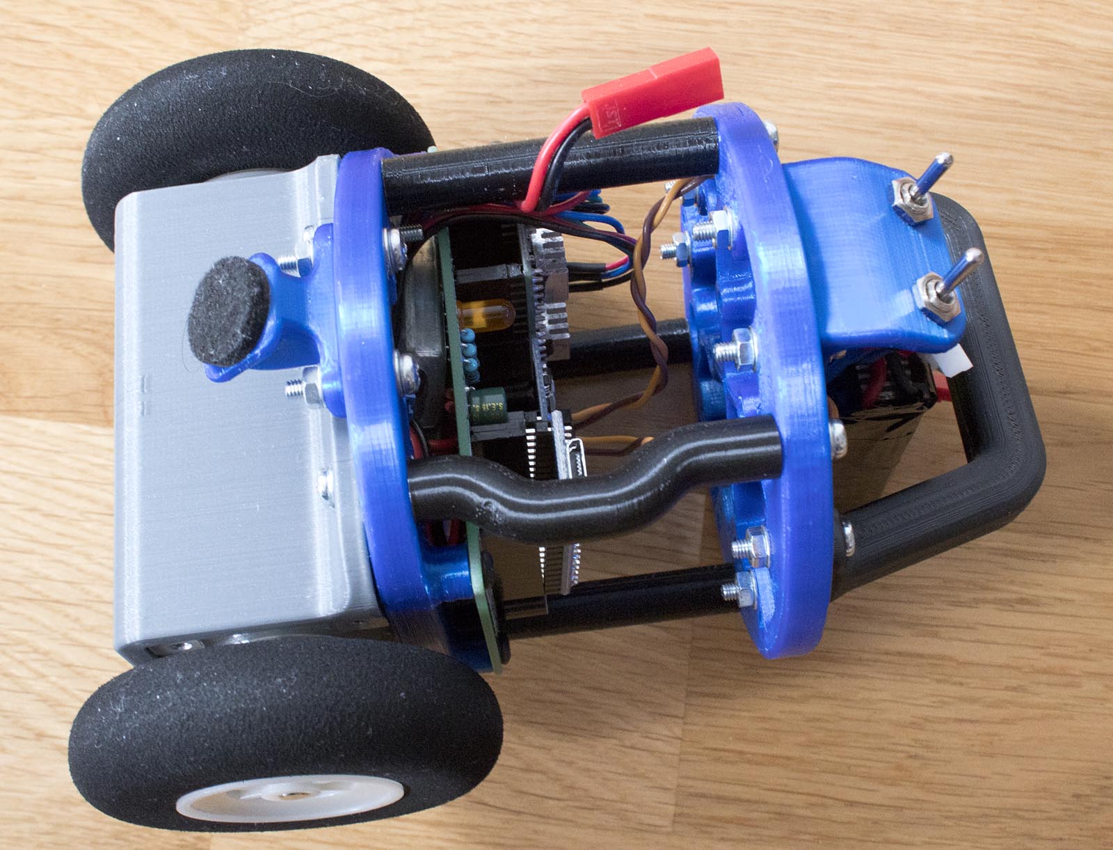
As can be seen in the images above, I realized late in the design process that one of the spacers was blocking the USB-port on the Arduino. Since I had already printed the top and bottom plates when I realized this, the simplest solution was to make a curved spacer that fitted around the connector.
Control theory
To balance the robot, a PID cascade is used. It is basically two connected PID controllers. One PID controller (the inner control loop) takes the difference between the desired angle and the current angle and calculates a speed for the motors. The second PID controller (the outer control loop) takes the difference between the motor speed and the setpoint speed as the input and calculates the desired angle.
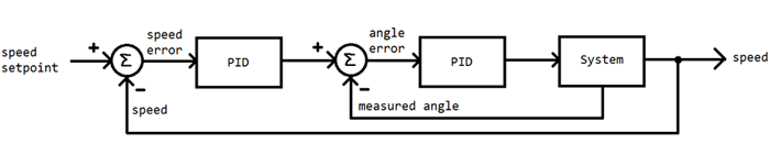
This control system allows the robot to return to its original position when disturbed. The robot is also capable of finding a new setpoint angle for balancing if the centre of gravity is moved, or the robot is standing on an inclined plane. Since I use stepper motors, no wheel encodes are needed for the feedback. The motors will always run at the speed they are commanded.
For example: If we want the robot to stand still, we can set the setpoint speed to 0. If the robot starts to drift forward (if the robot is front heavy, or if it is pushed) the I-part of the outer control loop will adjust the setpoint angle to lean back to try to get the speed to 0. This works because the integral of speed is position. The lean back angle will be proportional to the distance from the starting point. The P-part of the outer control loop makes the robot always lean slightly backwards relative to its travel speed, this dampens oscillations otherwise caused by the I-part, without the P-part, the robot would go back and forth indefinitely, and never come to a stop. No D-part is needed in the outer control loop.
When tuning this kind of system, I start with the inner control loop which calculates the motor speed based on the angle. I set the setpoint angle to 0 (straight up) and the I and D-gains to 0. Then increase the P-gain until I get oscillations. Then I slightly reduce the P-gain and add some I and D gain. When this is done correctly the robot should be able to balance, but it will drift away by itself, or when pushed. The robot should return to its straight-up angle relatively fast when pushed, and there should not be any high speed oscillations, vibrations, or to large overshoot. After this, the outer control loop the controls the setpoint angle based on the speed can be tuned. This is usually much easier, just add some P and I gains and experiment.
Arduino code
The Arduino runs the main loop which reads sensor data and balances the robot at 400Hz. Since this robot is quite small and can move fast, I have found that a relatively high refresh rate a needed to make it stable. The target loop-time can easily be adjusted with a constant in the code.
Hardware timers are used to generate the step-pulses to run the stepper motors. This is the reason I use the Arduino Pro Micro. It is the smallest Arduino available which has two 16 bit timers and a USB-interface for easy programming.
To keep things simple and understandable, I do not use the MPU-part of the MPU-6050 module. Instead, I just read the raw data from the sensors and do the sensor fusion myself. This is done with a simple complimentary filer. It works like this: An angle is calculated by integrating the gyro signal, then this angle is adjusted slightly based on another angle value calculated using accelerometer data and some basic trigonometry using the arctan-function. The “gyro-angle” has drift and is not very accurate, and the “accelerometer-angle” is very noisy and unusable by itself. The combination of those two results in a good and relatively noise-free angle estimation, that can be used by the PID controllers balancing the robot.
I have two auxiliary switches connected to digital pins 14 and 15. In version 1 of the code, one of the switched is used to toggle between standing still and going forward, and the other switch is used to turn on and off a function that performs random turns while standing still.
The robot will start balancing when it is not balancing and that is senses that its angle is close to 0 (straight up). While balancing the robot will stop if the angle difference between the setpoint angle and the current angle gets too large or if the current angle gets too large (if the robot leans two mush in any direction). The Arduino also monitors the battery voltage and stops the robot when the voltage gets too low.
The version 1.0 code does not use any third party libraries.
Download
You can download the code, schematic and STL-files for 3D printing if you want to make your own robot, similar to this one. I have also included the Gerber-files. My code and files are using creative commons license, please do not use my resources for commercial purposes.
Update 2017-10-13: New version of the code available in the downloadable folder. I have retuned the PID values to make the robot steadier. I have also increased the loop speed slightly. I am now using TMC2100 silent stepper motor drivers in the robot.
Update 2018-01-01: New version of the code available in the downloadable folder. I have added a simple obstacle avoidance behaviour and some other minor tweaks and adjustments. I have also retuned the PID values slightly again.
Download everything here (50MB)
If you want to modify my schematic or order my PCB design you can find the project on EasyEDA here: StepperMotorRobotController