 Overview
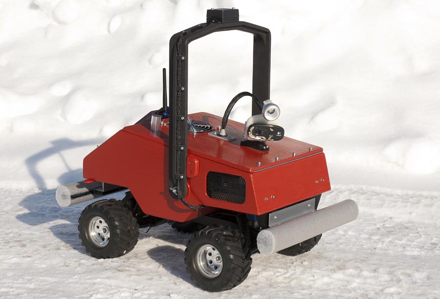
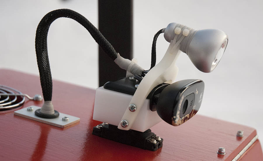
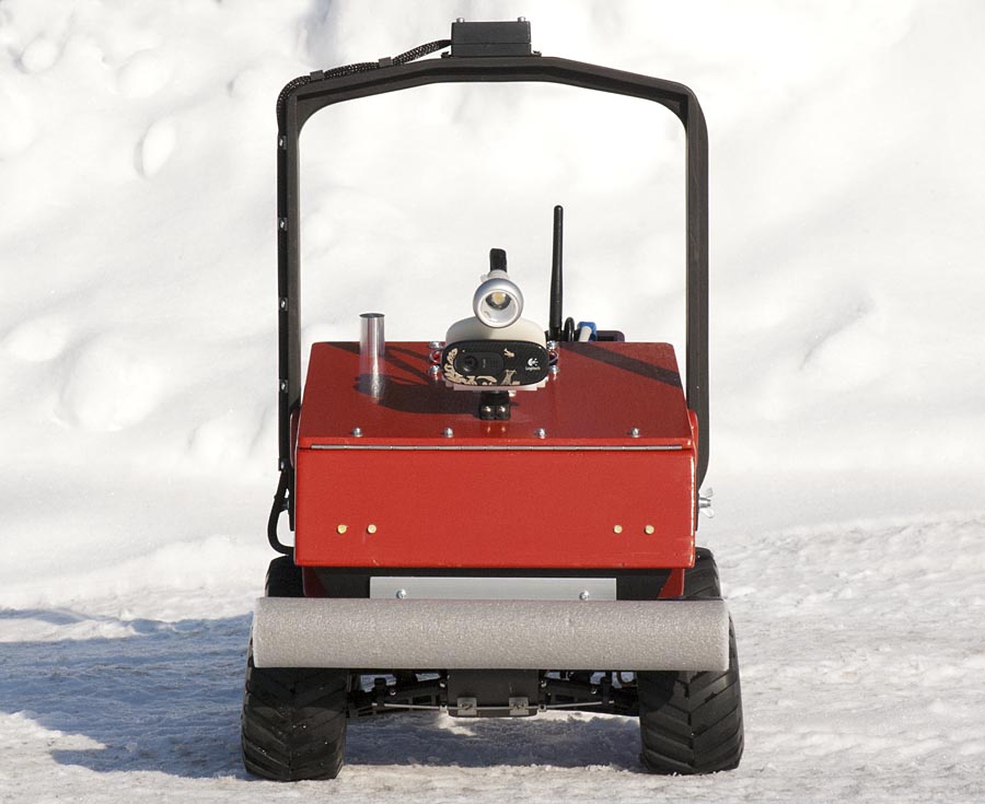
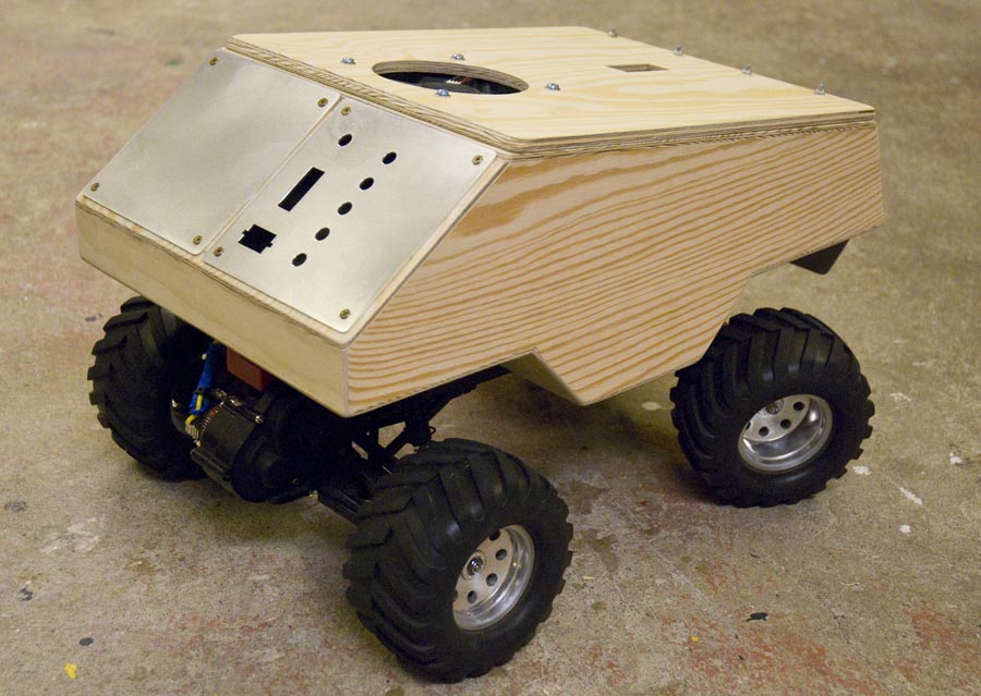
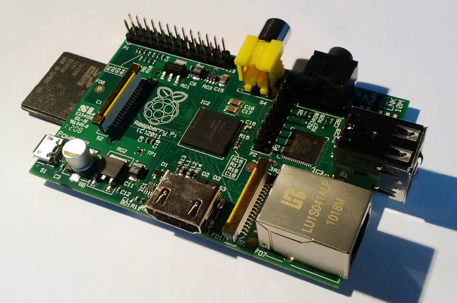
ArcRover, built in 2012, is an outdoor rover with GPS using a Raspberry Pi as the main computer. It is equipped with a WiFi router allowing me to log in and control it remotely with a laptop, and a web camera to stream images to a laptop as the rover is running, even if I am outdoors and there is no other WiFi network within range.
In this project, I will try to develop a robot that can efficiently navigate a waypoint route. To start with, the GPS will be the only sensor controlling the rover. Maybe I will add more sensors later. The objective of this project is to learn about controlling a robot with a “real” computer. I want to see what I can do when I have more computing power available. I also want to learn about Linux and other computer-related topics, like sending data over a network.
Raspberry Pi and Linux
When I started working with the Raspberry Pi it was very new. And there were not many examples and articles about it on the internet. The Raspberry Pi is running Linux, which I had no experience with at all. Therefore it was hard to get started. It was a lot to learn before I could get the robot to do anything. But after a while, I started to learn the basics and realized that it was a very powerful and fun platform to work with.
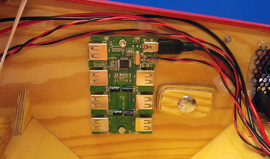
By default, the main programming language in Raspberry Pi is Python. I do not like it very much. I began programming in C++. but now I use Java instead. I have also managed to install some other programs enabling me to log in to the Raspberry Pi over the network using an SSH server (for terminal access only) and a VNC server to use the graphical desktop environment over the network. I can also start a video stream from the webcam which can be viewed in VLC player on another computer.
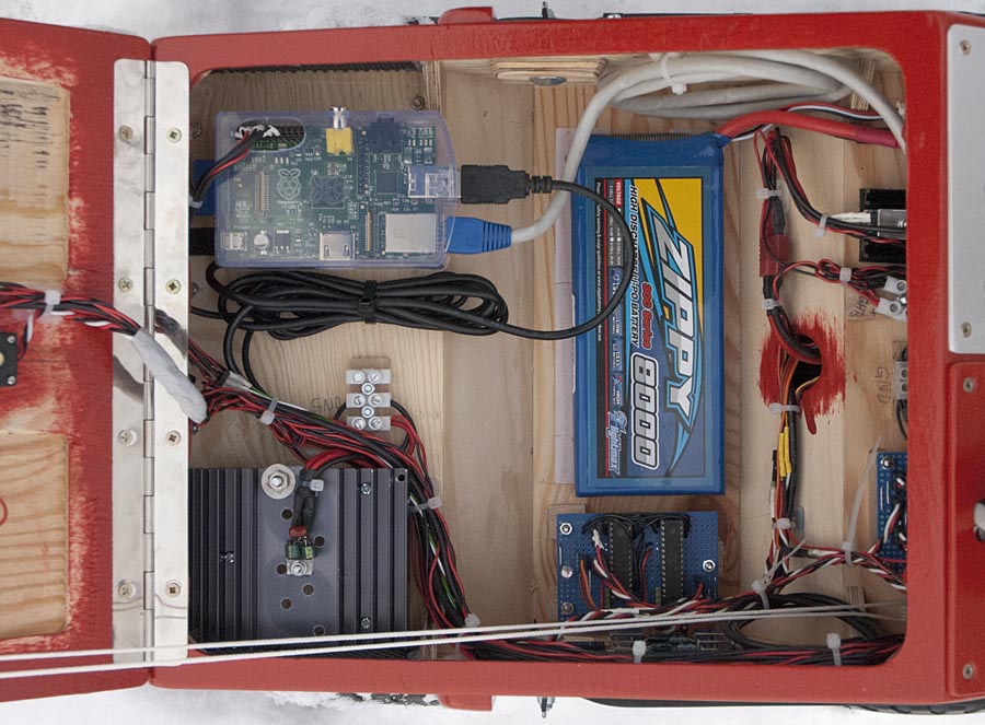
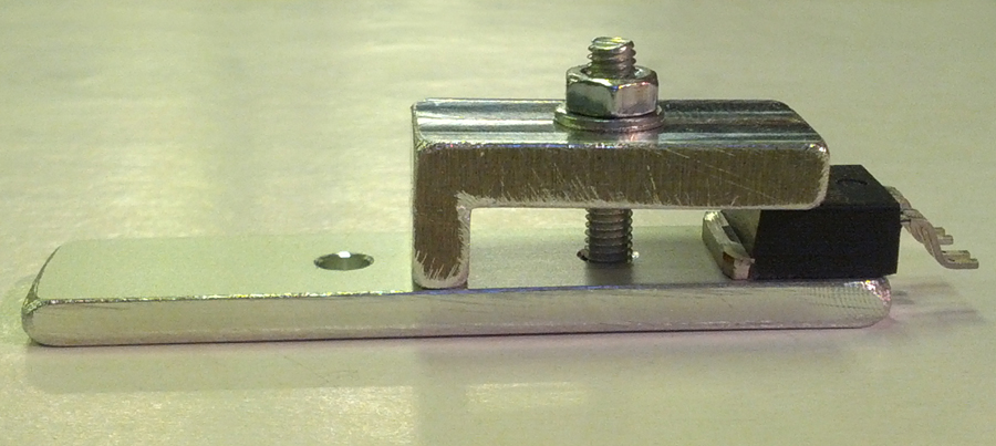
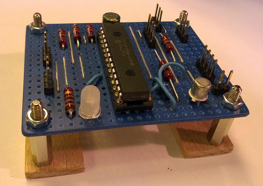
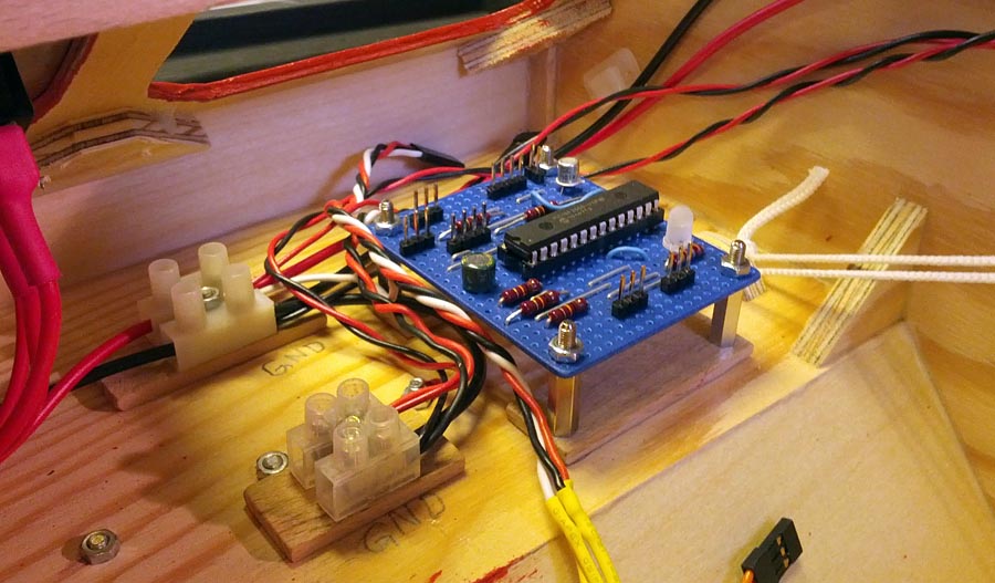
System layout
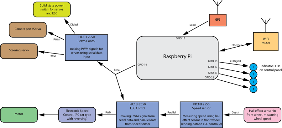
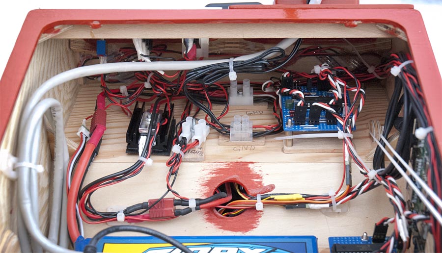
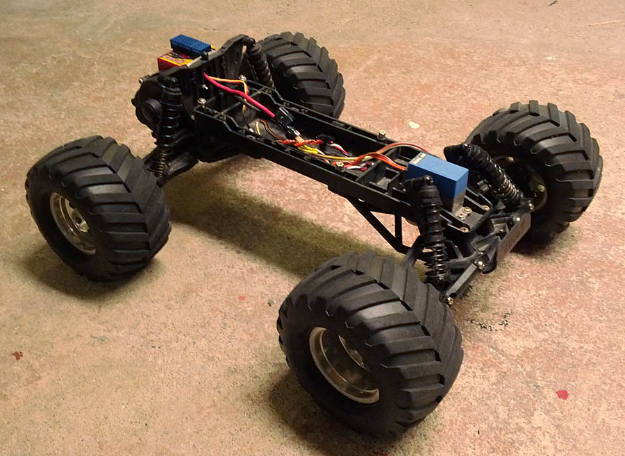
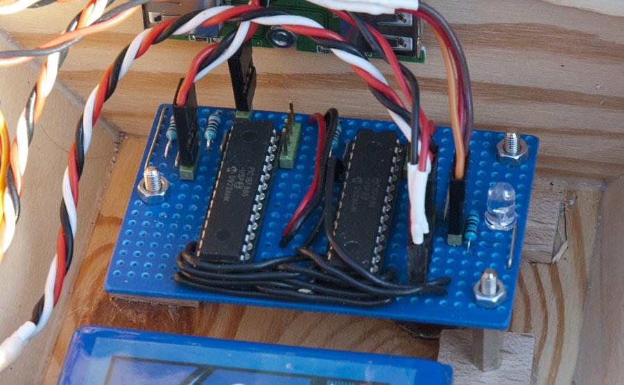
There are some PIC microcontrollers in this robot, controlling the servos and the ESC, used to control the motor speed. There is a hall-effect sensor on one of the front wheels that measure the speed of the robot, similar to my third robot. The power to the motor is adjusted by a PID algorithm and input data from this sensor. This makes the robot run at fairly the same speed on different kinds of surfaces. The Raspberry Pi controls the robot by sending serial data to the microcontrollers using the built-in COM port.
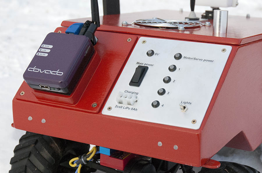
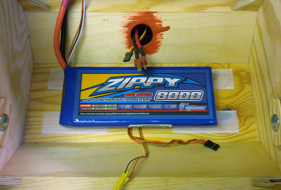
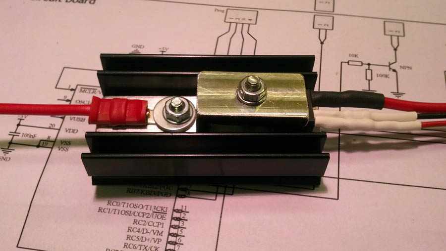
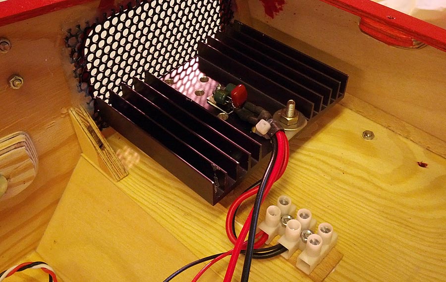
Power distribution
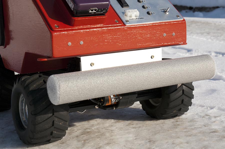
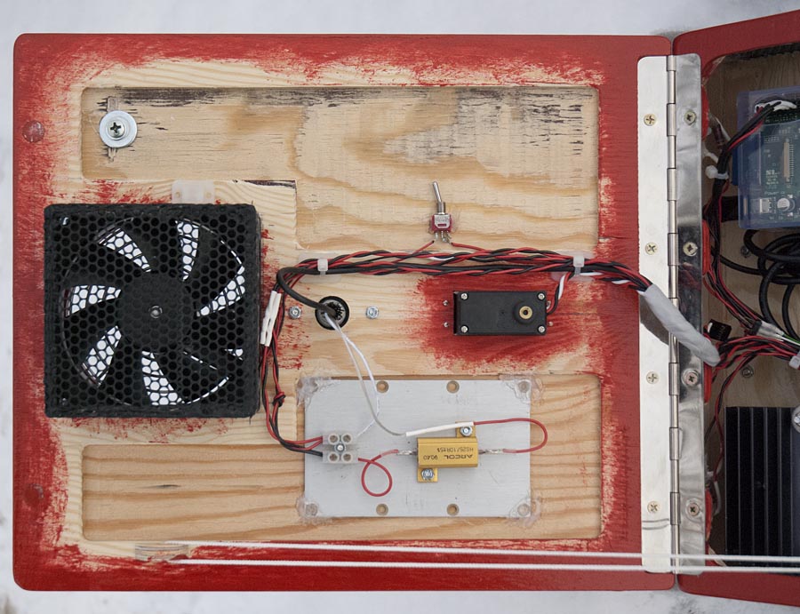
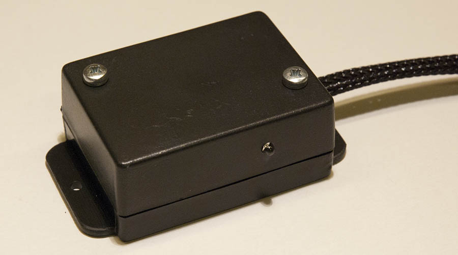
The robot is powered by a large 2-cell 8000mAh LiPo battery. A low-drop 5-volt linear regulator is powering the Raspberry Pi and the other electronics. If all systems are switched on simultaneously the rover consumes almost two amps of current. Therefore the regulator is mounted on a large heat sink.
Motor problems
One troublesome thing with this robot is the motor. The problems began when I was developing my third robot, the original motor got overheated and got destroyed. After that I replaced it with a slower motor (55T “crawler type”) with more torque. It worked better. But ArcRover is heavier and puts more stress on the motor, so it also got overheated when I was running the robot in some tall grass. Now it is replaced by a new, even slower 100T motor. I have realized that the gearing in this RC car is optimized for very high speeds, which makes it bad at low speeds.
GPS receiver
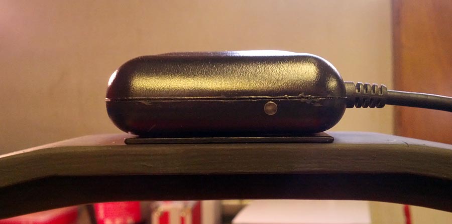
In the beginning, I was using a GPS receiver with a USB interface (BU-303) connected directly to the Raspberry Pi. It worked, but it was an old GPS running at only 1Hz. It was using a really slow baud rate of 4800bps. This became a problem when I realized that the serial library for Java did not work at that baud rate. I could not find a way to change the baud rate of the GPS, so I decided to replace it.
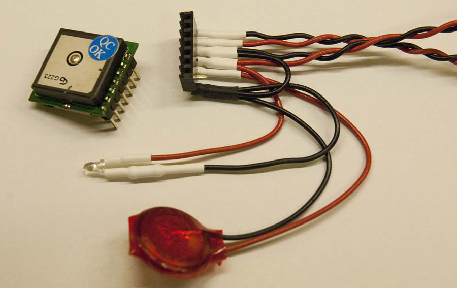
Now ArcRover uses a SUP500F. It runs at a higher baud rate of 115200bps. This GPS does not have USB, so the Raspberry Pi’s default serial port on the GPIO header is used instead. It can run at 10Hz update frequency, but I have found out that it is much more stable and accurate while running at 2Hz, so that is what I use.
First navigation tests in C++
I started to develop a program for ArcRover in C++. I came to a point where the rover was able to navigate a track of waypoints. I used Google Earth to make a GPS track. The track was exported as a KML-file, which was converted to a GPX-file. This file was loaded and used by the navigation program in the rover. The ArcRover ran the track just by steering the wheels proportionally to the error between the rovers course and the heading to the waypoint. The program uses the WiringPi library to control the LEDs on the GPIO pins and the serial communication to the PIC processors.
This C++ program is used in the video at the top of this page.
Software development in Java
There are two reasons I prefer to use Java instead of C++. Firstly, it is much easier to set up a network communication between a server (the rover) and a client (a laptop) to send data over the network. Secondly, I like Java more than C++. Java is a more flexible programming language, and I also have more experience with Java than C++. Java also has its flaws. Java runs on a virtual machine, which makes it less suitable for time-critical applications. But I do not think that will be a large problem in my application.
To communicate with the rest of the robot’s systems I use the pi4j Library which provides direct access to the GPIO pins and serial communication. This Java library is built upon the WiringPi library.
Manuel remote control using an Android application
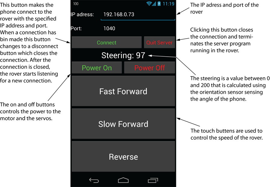
Even though this rover is designed for autonomous navigation this video shows how it can be controlled over WiFi using a homemade Android app.
The App connects to a server program written in Java running in the rover. When the app is connected to the rover it sends a string of data containing desired rover speed, steering, and power switch state approximately 20 times a second. The server program in the rover receives the data and sends it away to the PIC processors.
The server program can be configured to run on boot-up. By doing this there is no need to have a computer to log in to the Raspberry Pi using SSH. Just power on the rover and use to app to drive it.
Possible future development
The ArcRover is far from complete. There are a lot of things I would like to test, and the Raspberry Pi makes the possibility for further development almost endless. A few of the things I want to do is:
- Continue developing the waypoint navigation to make the rover use PID algorithms instead of just proportional steering to drive the track.
- Make the rover steer towards the line between two waypoints instead of just to the next waypoint.
- Develop some kind of program running in a laptop communicating with the rover. I want this program to be able to start an autonomous mission, as well as drive the rover manually.
- Specify an area in which the rover should drive autonomously.

Great project! Have you worked on it more since this post? I am working on a similar project that uses the R-Pi for the main navigation processor and an Arduino for steering, speed control, etc. My test platform is an RC car similar to yours (not nearly as nice though). The end goal is to put all this into a small autonomous boat and send it out into the ocean!
Would you be willing to share your C++ code for reading the Google Earth file export and doing the navigation? Do you have a GIT repo somewhere? I have some very crude code in place (written in C and C++ and using WiringPi as well) that sorta works but I’m trying to combine a tilt-compensated compass along with the GPS. Did you figure out how to get the robot to follow the line between way points? Thanks for any help! /Charlie
I did loose the interest in this project, but I may revisit it in the future. My conclusion is that I need more sensors to get my rover to work good. A compass and maybe a gyro is a good idea I think. On a boat you can probably get away with a GPS I think, at least if you have a fast GPS. I have problems when the rover makes fast turns, slow turns and straight driving is no problems.
When it comes to the “line-following” I realized that a PID controller or similar is necessary here. Using just propositional control just makes things worse. I did implement it in Java, but I did not have a chance to test it cause of other problems. But I still think that calculating the distance from the rovers position to the line between the last and next waypoint, and using that as i input to a PID controller is a good idea.
I do not have a GIT-repo, but here is a small example that demonstrates the code I use for reading the gpx-file: The code is very simple and this may not be the best way to do this, but it works. Tell me if you have any problems.
could u give codes of this project ?
This is an old project. Last time I worked on it was a few years ago. I made a few different things: remote control using an Android app was one project, and GPS navigation was another. Unfortunately I lost some of the code due to computer problems. Also I had problems with the RC car it is built on, the gearing ratio is optimized for higher speeds, which causes to motors go get burnt out when driving slowly in grass. Maybe I will make another similar outdoor robot in the future based on some other chassie, but for now, I think you can find better information and code examples about GPS navigation elsewhere else on the internet.