Multirotors has been a growing part of the RC hobby for a while now. I wanted to build my own in a way that makes it stand out from other multirotors. I decided to build a quad because of the simplicity in the design, compared to other types of multirotors. No motors needs to be tiltable like on a tricopter, and of course it is cheaper to build quad compared to a hexacopter or a octacopter.
Construction
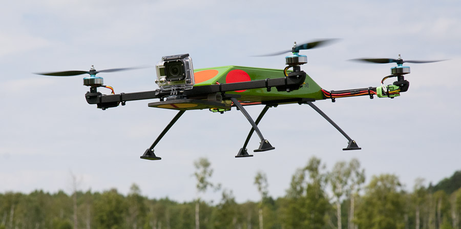
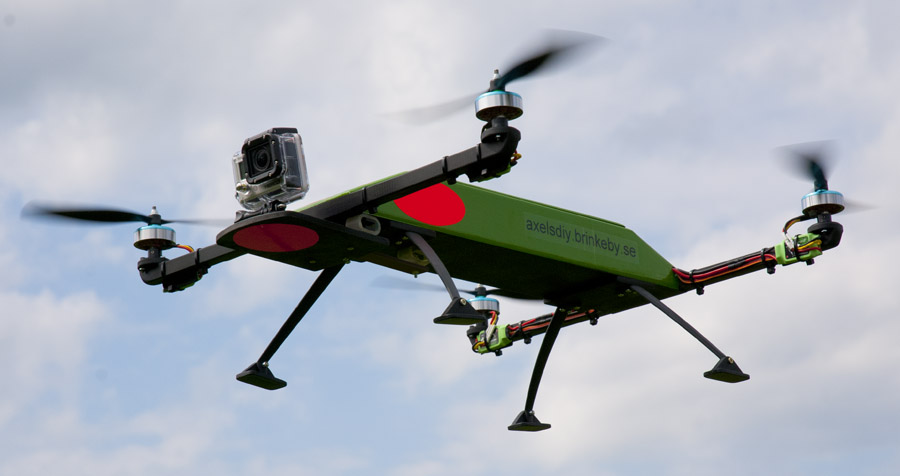
The frame is built entirely out of wood. The motors form a symmetrical square with a side length of 46 centimeters. The motor booms are 15×15 millimeter pine wood. The electronics box is made out of balsa wood and cowered using Oracover, in the same way as a traditional wood airplane. The main purpose of the box is to protect the electronics in case of a crash. I have used plastic landing gears intended for model airplanes, but instead of wheels, I have made small plates out of plywood.
Features
I use the following setup:
- Flight controller: KK2.0 board
- Motors: DT750
- ESCs: 20A Opto Multistar
- Batteries: two 3 cell 2650mAh LiPo connected in parallel
- Receiver: FASST compatible orange receiver
- 5V regulator: 7805 to power the ESCs and the flight controller board
- Diodes: BYV123 dual schottky diodes to connect the batteries in parallel
 The two batteries are connected in parallel using diodes. See the diagram. This prevents current to flow between the batteries. The battery with the highest voltage will be used first until both batteries has the same voltage. Then the batteries will be discharged simultaneously. This technique also adds redundancy to the system. If one battery fails, the quad will still fly on the other battery. three dual schottky diodes are used to be able the handle the current.
A standard 7805 voltage regulator supplies 5V to the flight controller board and the ESCs, since the ESCs I use do not have a built in BEC.
To monitor the voltage of the batteries I use the built in voltage alarm feature in the KK1.0 board. If the voltage gets tow low, a buzzer goes off, telling me to land.
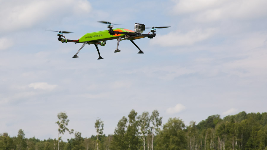
Flying
Flying the quadcopter is really exiting. I have not flown any other multicopters so I do not have much to compare it against. But I have flown a normal model helicopter. The quad is definitely easier to fly. The quad flies very symmetrically compared to a normal helicopter that is constantly pushed to the side by the tail rotor. This makes it possible to fly the quad with very high precision.
The KK2.0 board does an amazing work in stabilizing the quad. It can hover with no stick input for a couple of seconds without drifting away to far. Even in some wind it seems to be stable. I have not tuned the stabilizing parameters. It seems to fly great with the stock values.
Plans
Plans are available for download in pdf here:
Note #1: All dimensions are in millimeters. The plans are not in scale 1:1.
Note #2: The camera plate is mounted directly to the fuselage on the plans. Later I mounted it using pieces of silicon hoses to dampen vibrations. This results in steadier video. See the images below.
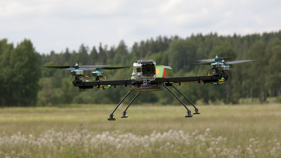
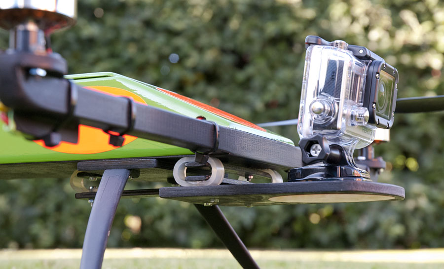
The camera is mounted to the quadcopter using three pieces of silicone tubing. This acts as a dampening system. dampening system
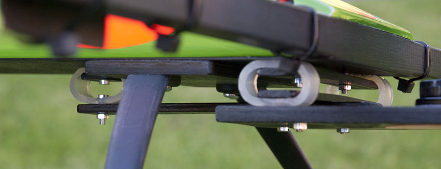
Detail image of the damping system.
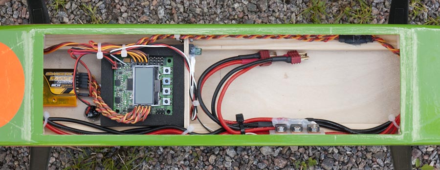
The electronics bay.
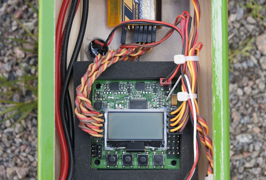
A KK2.0 flight controller board to stabilise the quad.
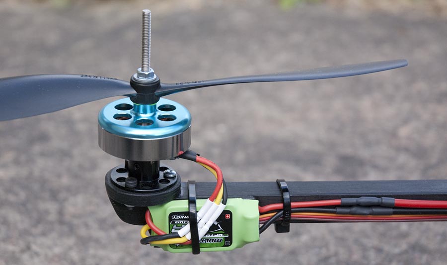
DT750 motors and 20A opto Multistar ESCs.
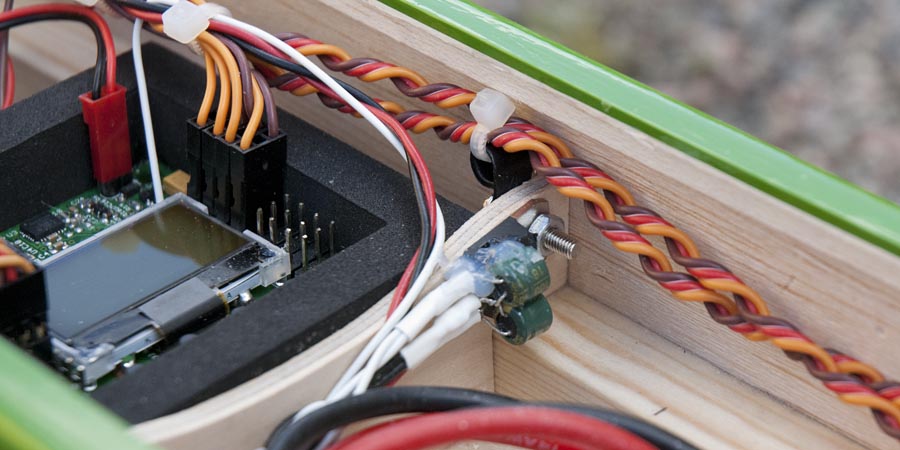
A 7805 Voltage regulator supplies the flight controller board and the ESCs with 5V.
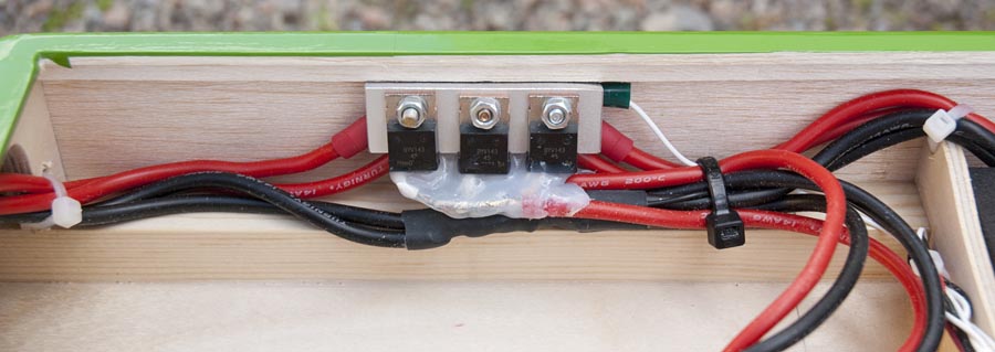
Three BYV143 diodes are connected in parallel. The diodes makes it possible to connect two separate batteries to power the quad, without current flowing between the batteries.
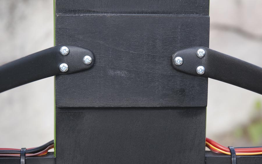
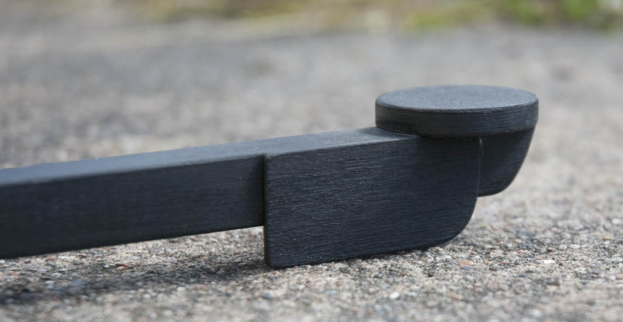
I have used landing gears in plastic that are intended for model airplanes. The landing gears are mounted the the fuselage using self threading wood screws.
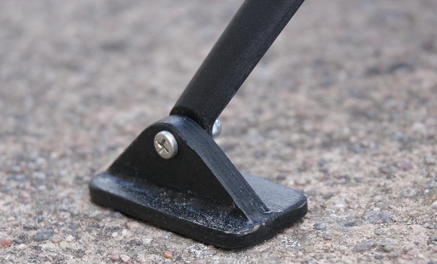
Instead of wheels, I have made “feet” out of plywood.
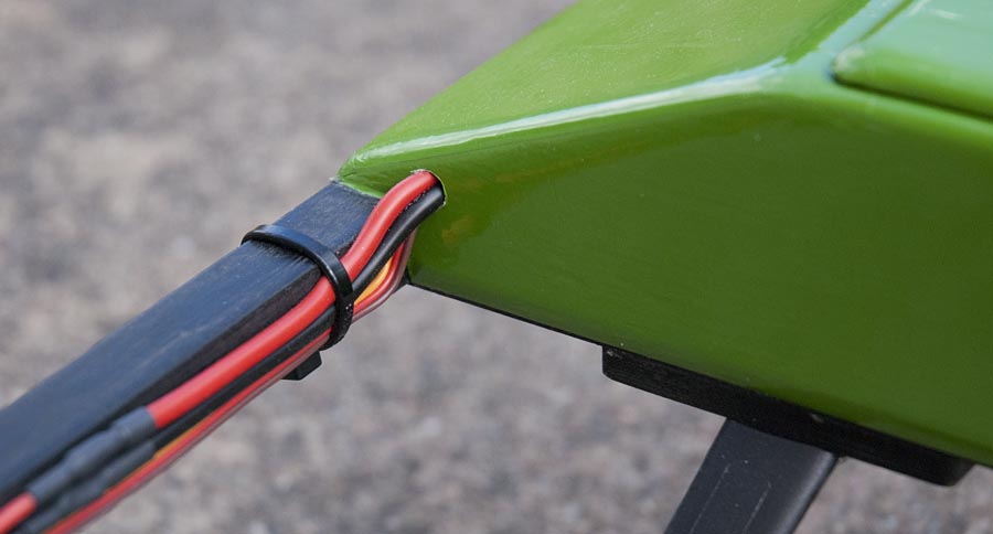
The cables to the motors are mounted the the arms using zip ties.
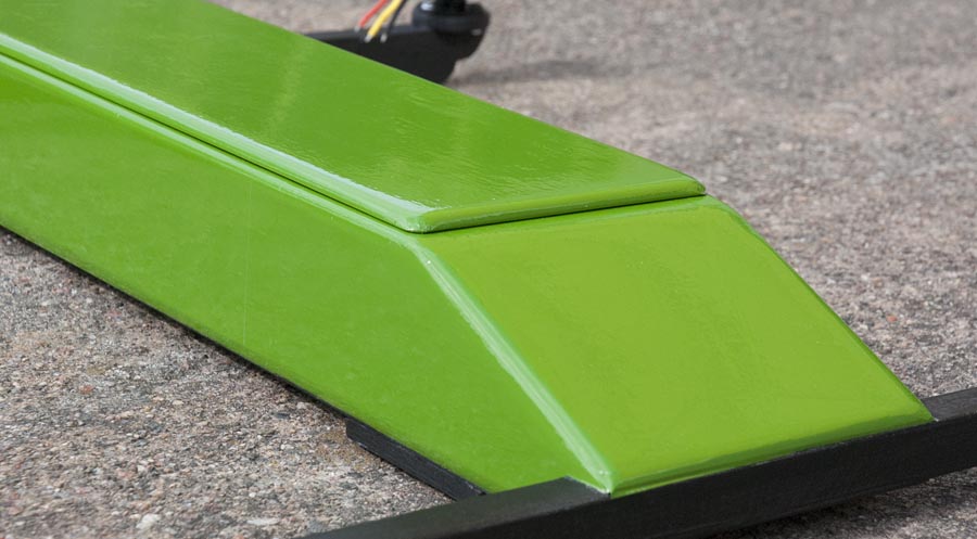
The hatch is friction fitted the the fuselage.
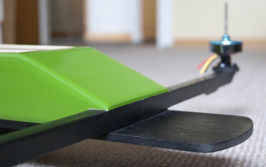
The image shows the seam between the painted wood and the wood that are by covered by Oracover.
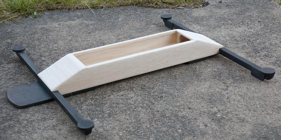
The electronics box is built out of balsa wood.
Motor and ESC mounts.
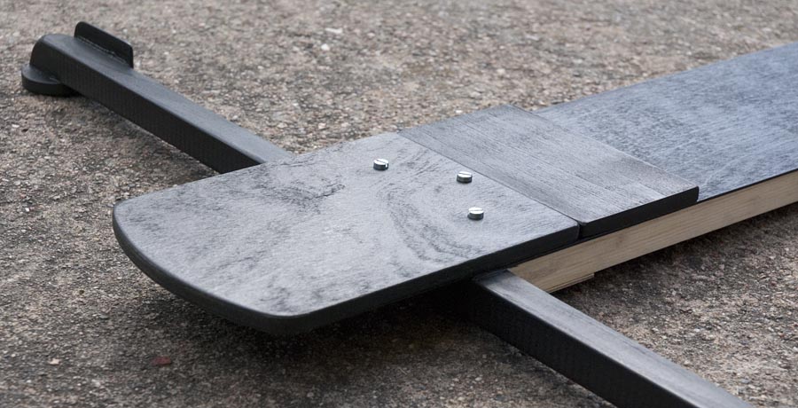
Before I made the dampening system for the camera plate, it was mounted to the fuselage using three screws. This resulted in some “jello-effect” in the video due to vibrations.
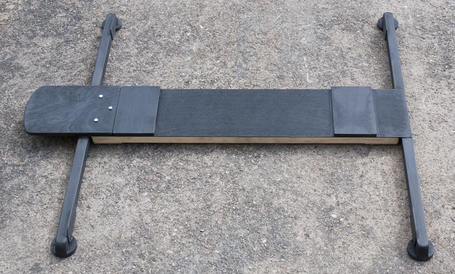
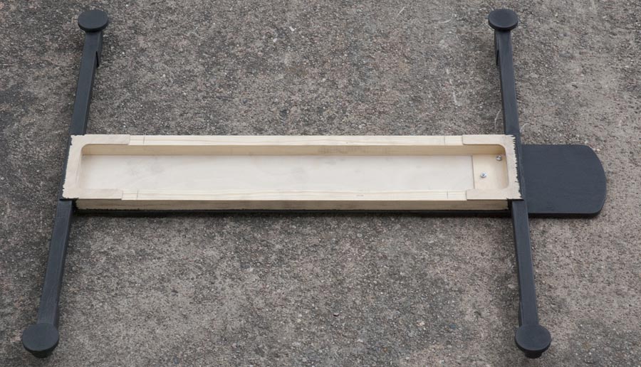
Bottom view of the frame. All visible arias are spray painted black.
Top view of the frame.
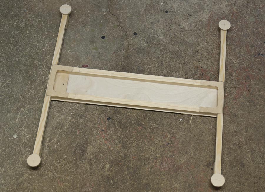
The frame is made of 15×15 mm quare pine wood and a 1mm thick piece of plywood in the bottom.