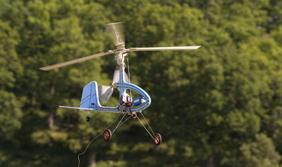
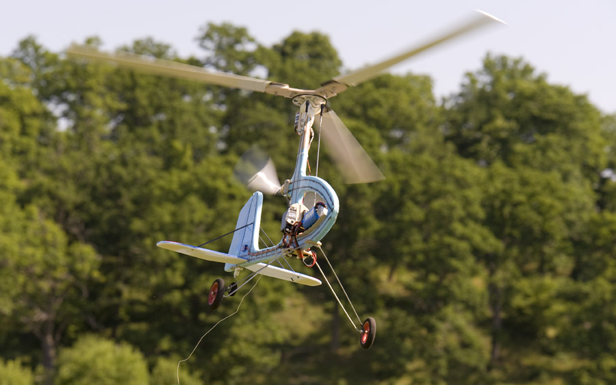
An autogyro is a combination of an airplane and a helicopter. It has a rotor generating lift like a helicopter, but the rotor is not powered in flight. The vehicle is driven forward to remain in the air, this is done by a normal propeller, just like an airplane. The vehicle is controlled the same way as an airplane, but it is a totally different experience to fly.
Pre-rotator
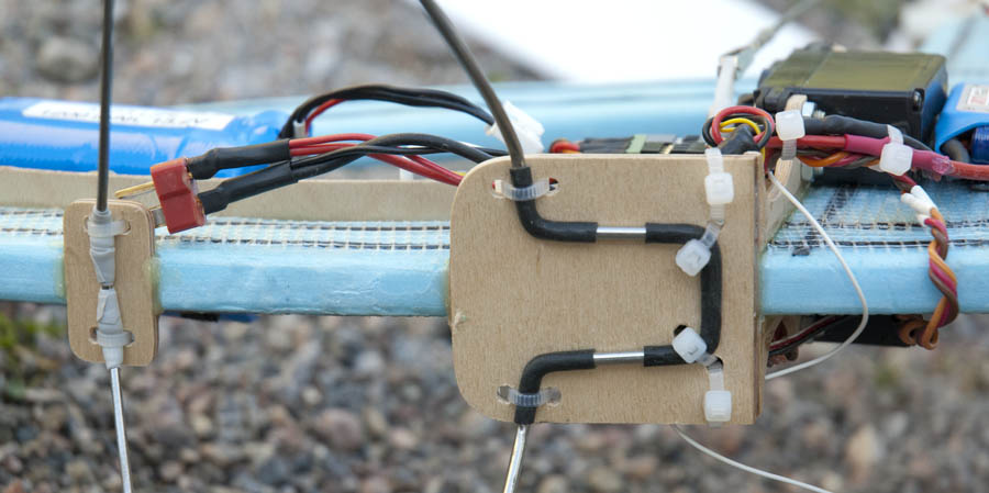
The takeoff can be very tricky with an RC autogyro. The difficult part is getting the rotor to spin fast enough, especially when there is no wind. I have solved this problem by adding an electric starting mechanism for the main rotor on my autogyro. The pre-rotator is based on a friction drive system with a brushed speed 280 motor that is engaged when the rotor is tilted fully backward. The motor is automatically controlled by a PIC 12F683 microprocessor that I have programmed in C. The microprocessor decodes the signals going to the servos, by doing this, it can sense when the rotor is tilted backward and ramp up the speed of the starter motor. The microprocessor drives the motor using an IPS031 power switch modulated with PWM. The speed is ramped up to minimize the risk of the drive wheels slipping.
Rotor head
The rotor head is one of the most critical parts on an autogyro. Mine is homemade. The rotor blades are mounted to the rotor head using hinges that are angled in a way that makes the blades decrease their angle of attack when they are bent upwards by their own lifting force. This reduces the difference in lifting force of the blades going backward opposite to the direction of flight and the blades that go forward against the direction of flight. If the blades are mounted solidly to the hub, the rotor needs to be tilted a lot to compensate for that. Actually, in my case, the rotor is tilted the opposite way because my hinges are to soft. Both the angle of the hinges and the flexibility of the material used needs to be right for the rotor to be level while flying straight forward.
Construction
The fuselage is built of 10mm thick blue foam, reinforced with fiberglas and carbon fibre strings soaked in epoxy. I use a 4 cell LiFe battery in my autogyro. The voltage is a little bit higher than a 3 cell LiPo battery. It is also more durable and can be charged faster than a LiPo battery. However the is a little bit heavy, and the capacity is on the low side for the current consumption. This results in a relatively short flying time. But I still prefer it over LiPo batteries.
My setup:
- Axi 2212/26 (Gold Line)
- 10×4.7 propeller cut down to 225mm diameter
- JETI Model 19A ESC
- Old Hitec 5CH, 35Mhz radio system
- JR NES-537 servos for tilting the main rotor
- HTX 900 servo for the rudder
- 4 Cell, 13.2V, 1200mAh, A123 LiFePO4 battery
- Brushed 6V Speed 280 motor for the rotor start mechanism
Other data:
- Rotor diameter: 980 millimeters
- Length: 690 millimeters
- Weight: 870 grams
- Flight time: 5 to 8 minutes
Flying
Even though the autogyro is controlled the same way as an airplane, it needs to be flown in a special way. There are some special things to be aware of.
My autogyro is heavy, and it does not have a lot of excess power, therefore it is not possible to climb rapidly. This makes it really important to plan the flight a few turns ahead to avoid colliding with things.
One interesting thing is that it is imposable to stall by flying to slow. If the power goes out during flight, or the throttle is decreased, the autogyro just falls slowly straight down. This vertical speed is usually low enough to prevent any big damage on the airframe. I have also found that it is usually possible the decrease the vertical speed even more just before the gyro hits the ground by tilting the rotor fully backwards. However it is important to keep the rotor spinning. This is done by never push the autogyro into situations were it will experience low or negative g forces. Therefore it is not possible to fly up side down or make any extreme aerobatics.
Under a normal flight I keep the motor power above 50% all the time, even during the landing. I stop the motor after the gyro has landed. The vehicle has larger speed envelope then one would expect. It is possible to fly pretty slow by tilting the rotor almost fully backwards and controlling the altitude with the throttle. Cruising speed is around 80% motor power. To fly fast, it is possible to set the motor power to 100% and control the altitude by tilting the rotor. To fly straight forward it is necessary to tilt the rotor almost fully forward.
Plans
I have got some questions about plans for my autogyro, Therefore I have put together a document with detailed high resolution pictures with annotations. The pdf is available for download here:
Note that this document is based on my autogyro, not vice versa. I have made the document using pictures instead of making a complete CAD drawing to save time. However all the critical dimensions should be included in the document.
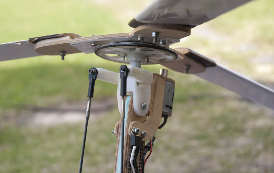
Rotor head. The large friction drive wheel is from an old helicopter and the small one is custom made from a piece of aluminum. The gear ratio is approximately 1:10. The image also shows how the fuselage is reinforced with 3 mm plywood on both sides where the rotor tilting mechanism is mounted to the fuselage.
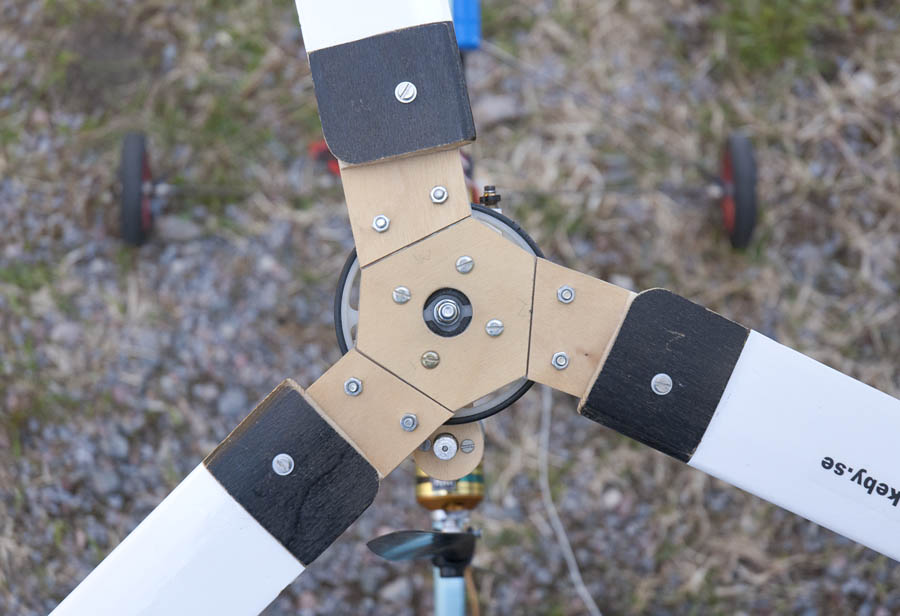
This images clearly shows the angled hinges between the hub and the blades.
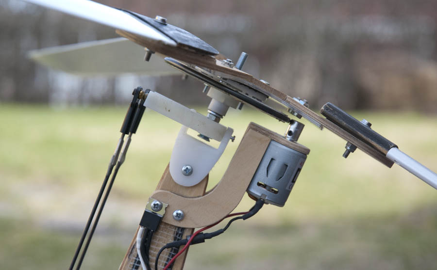
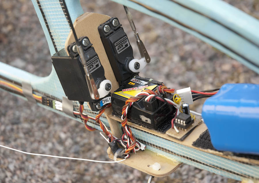
The starter motor is engaged when the rotor is tilted fully backward. The power switch controlling the motor is also visible.
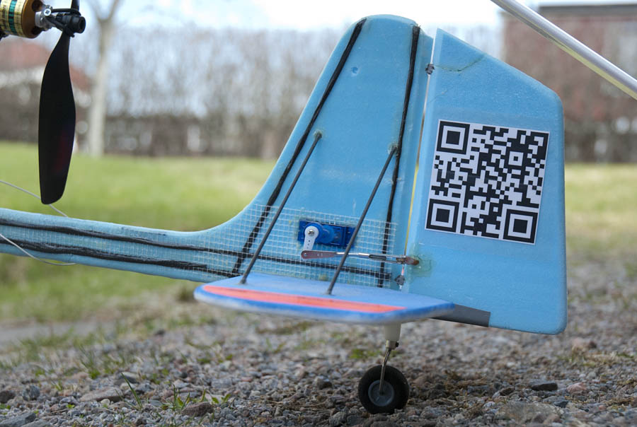
The steerable tail wheel is located in line with the rudder hinge to decrease stress on the small servo.
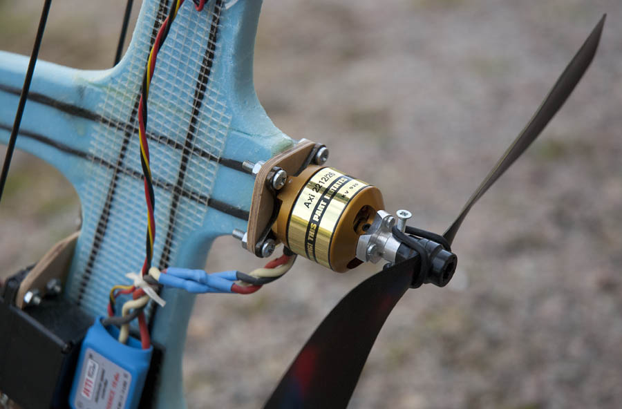
The main motor is an Axi 2212/26. The prop saver is not necessary here, but I did not have an ordinary propeller mount, therefore I use it.
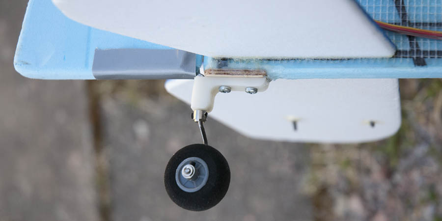
The tail wheel is mounted to the fuselage using a custom machined delrin bracket.
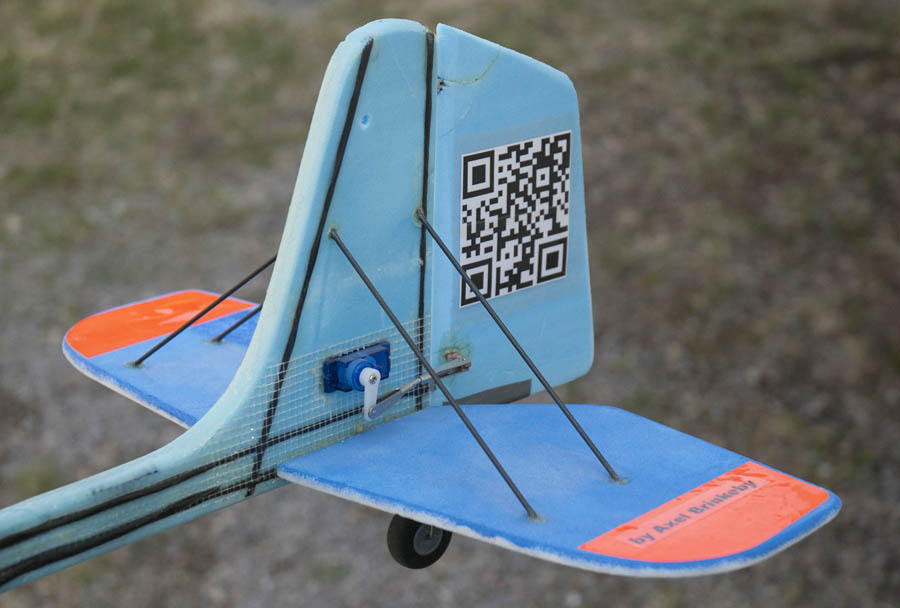
The stabilizer is reinforced with some carbon fiber rods.
The landing gear is mounted to the fuselage using zip ties.
Two strong servos tilt the rotor.
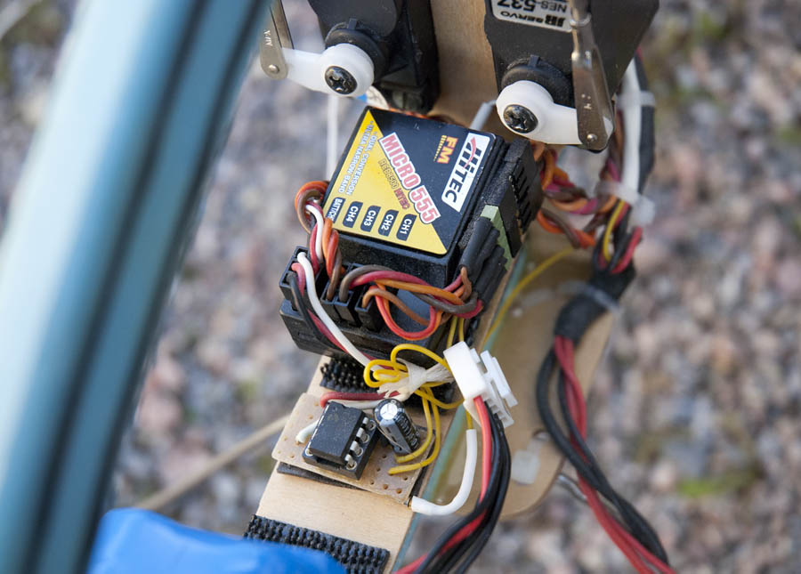
This image shows the PIC12F683 microprocessor that controls the rotor start mechanism.
Hi Axel I have wanted to build one of your Autogyro for some time and hope to get started this winter
Can you give me more info about your prerotator controller parts circuit etc
Many thanks Joe