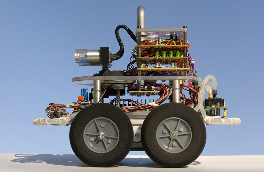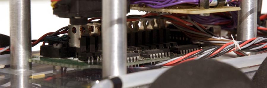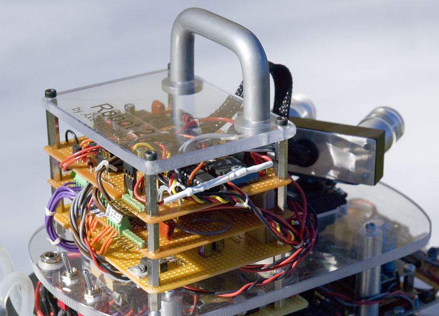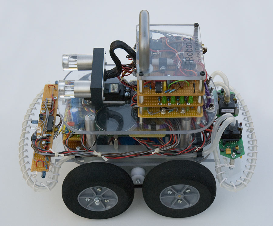
This is my second robot project. I built and programmed it in 2010. It can drive around autonomously in an indoor environment and avoid obstacles, just like my first robot, but this one has more sensors and more complex behavior. This robot is based on a number of separate systems with individual PIC microcontrollers talking to each other.
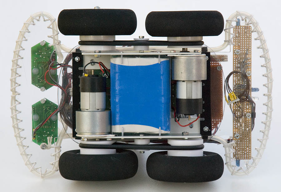
I have made all the parts of the robot myself, including the main ultrasonic rangefinder. The only exception is the H-bridges, and of course the pneumatic pressure sensors. The H-bridges are a surplus item containing IPS-031 power switches and optocouplers. The H-bridges are controlled by two PIC microcontrollers, one for each motor.
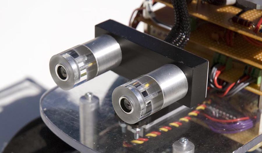
The ultrasonic rangefinder is measuring the distance to an obstacle by sending a burst of sound waves and measuring the time until the eco returns. This is the same working principle as HC-SR04 sensors, and many others are available on the market. My design here is not as efficient, and it has a lot shorter range than the commercial ones, but I have learned a lot by building it myself.
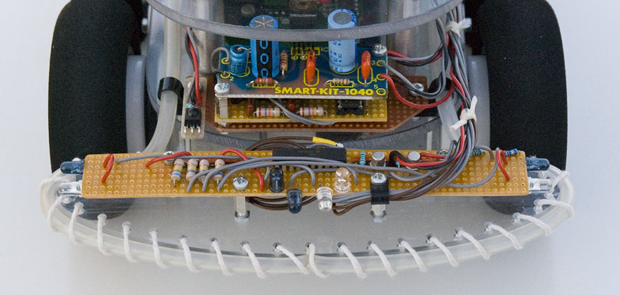
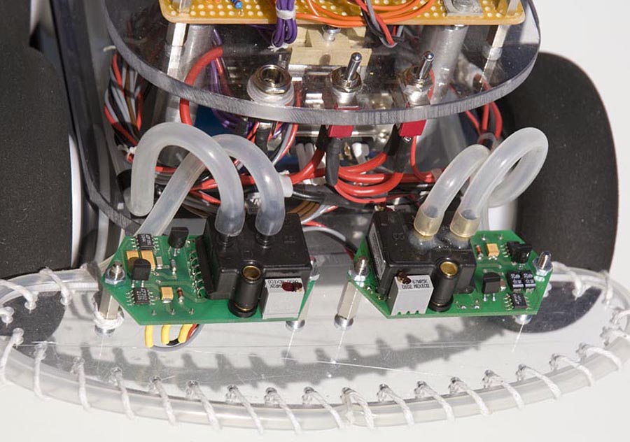
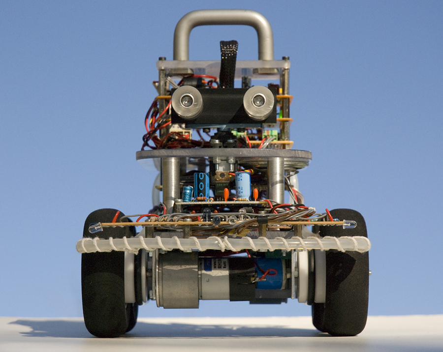
For the bumper sensors, I use silicon hoses mounted in the front and back of the robot which is connected to a couple of pneumatic pressure sensors. When the robot hits an obstacle the silicon hose gets squished together, creating an increase in air pressure inside the hose. The analog pressure outputs are converted to digital by two PIC microcontrollers, which also control some LEDs mounted in the bumpers.
The robot is also equipped with four infrared sensors mounted on the front bumper. Each “infrared sensor” consists of one infrared LED and one phototransistor. There is one set facing forward, one upward, one left, and one right. The upward-facing sensor is just to prevent the robot from driving under beds or other furniture. All four sensors are controlled by a single PIC microcontroller. The analog signals from the phototransistors are measured with and without the IR LEDs on. If the difference is greater than a specified number there is an obstacle in that direction. The microcontroller sends this data as simple binary signals to the main microcontroller as four digital signals, one for each direction.
To give the robot a little bit more personality I have also equipped it with a SpeakJet voice synthesizer chip. The Speaker is connected to the SpeakJet through an audio amplifier. That makes the robot able to speak really loud if I want it to. The SpeakJet also makes some beeps and other sound-effect when the robot sees obstacles.
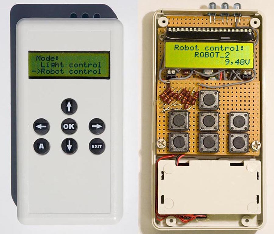
All those different systems are connected to a main microcontroller, running at 20MHz. This microcontroller also listens to an IR receiver, which can be used to control the robot using a homebuilt remote control. This remote control can also be used for completely different purposes, like controlling the lights in my room.