I have been experimenting with making my own LED light systems for RC planes for a while now. I first made my “RC plane hub” for one of my planes in 2019. It was a combination of a LED light system and gyro stabilization. More about that here: https://axelsdiy.brinkeby.se/?m=201911
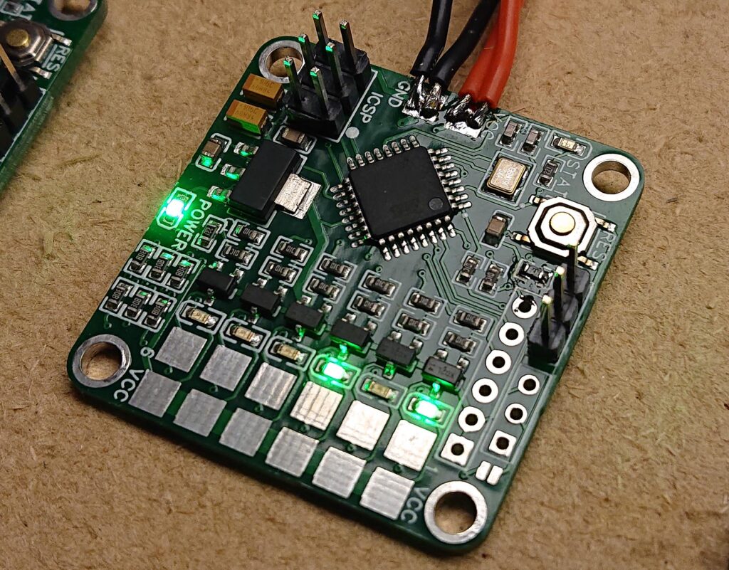
Later I wanted a small simple standalone system that could easily be installed in any plane. I first made some experiments by just connecting a couple of transistors and LEDs to an Arduino Nano. After a bit of prototyping I made a custom PCB with a ATmega328 processor and some MOSFETs for controlling the LEDs.

The idea is that this board is connected to the full battery voltage of the RC plane, and the outputs are connected to the LEDs. The LEDs themselves are connected on groups of three in series with a current limiting resistor adjusted to the LED type used and the battery voltage. The ATmega328 processor (same as Arduino Uno and Nano) reads a standard servo signal and controls and flashes the LED outputs in different ways depending on the input. This alows the pilot to control the LED from the RC radio.
I usually fly my RC planes on 4 cell Li-ion batteries. They are just over 16 volts fully charged and 12 volts when discharged. This causes the LEDs to be bright at the beginning of the flight and pretty dim at the end. Therefore I usually connected one of those small switching adjustable DC-DC converter boards between the flight battery and my LED board to convert the input voltage to 12 volts. When also adjusting the current limiting resistors for the LEDs to 12 volts this works quite well.
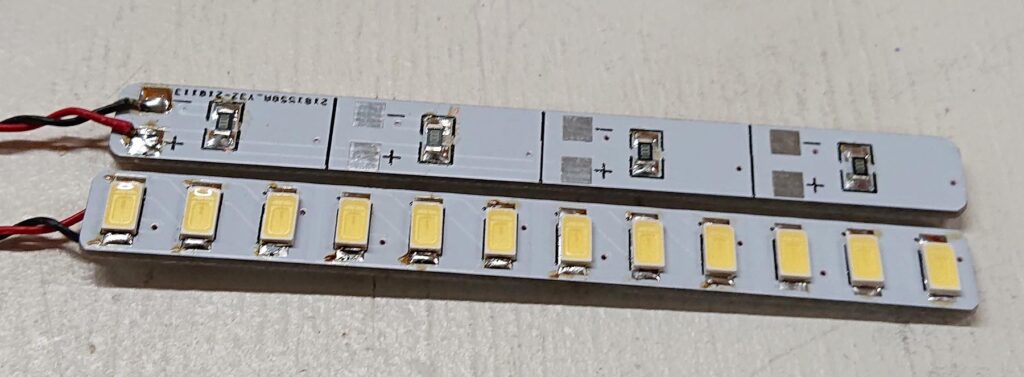
For the LEDs themself I use cold white surface mount LEDs for landing lights and strobe lights. I have made my own custom PCBs for them, as can be seen in the video above. For the colored navigation lights, I use standard 5 mm LEDs, of the brightest type I can find.

Later I made a new version of my custom LED controller board with a built-in fixed 12V switching regulator. Otherwise, it is the same processor, MOSFETs, and software as the first. I also skipped the indicator LEDs for each channel to save space on the PCB.
The new board is 60 x 25 mm. The 12V regulator can supply up to 3A to the LEDs. The MOSFETs can handle up to 3A each. Whish is a lot more than needed. The input voltage to the board can be up to 40V, or 10 li-ion cells in series. If the input voltage is lower than 12V the LEDs and the board will still work, but the LEDs will no be as bright.
Here is a link to my Arduino code: http://brinkeby.se/downloads/RCplaneLightSystemV2.zip
Feel free to use and modify the code as you like. This code can also be used an any standard Arduino Uno or Nano, not just my custom board
Here is my EasyEDA project with the PCB design: https://easyeda.com/editor#id=|d7bd0d7576e04ff88b89458a67529799|d44eedf4a12541269b71d3d20c136a3d

