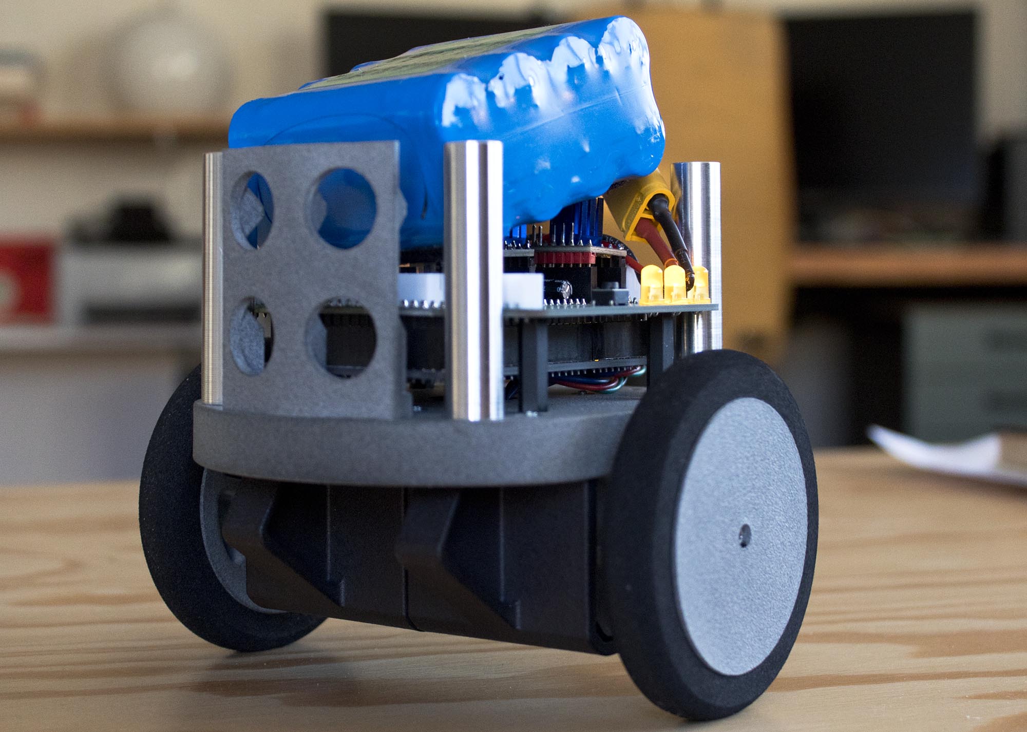
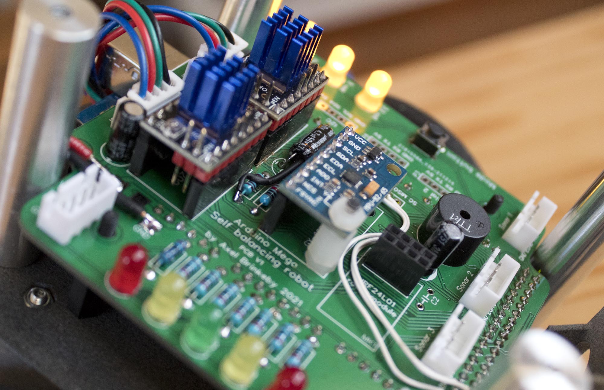
Made some progress on the balancing robot project. In this video, I made the first version of the PCB. It had a few problems but I still got the robot to balance. Some of the problems included:
- Design error with the voltage divider and filter capacitor for the battery voltage measuring. Capacitor blew up 🙂
- I forgot to connect the MISO, MOSI and SCK lines for the SPI bus.
- Problem with the fotprint for the wireless module.
- And a few more minior things…
Apparently, I need to check everything more carefully. Especially with the schematic, before I start to design the PCB itself. I hade also learned from many previous PCB projects that I have made, including this one, that you always need to create important/special component footprints yourself. Comunity-made footprints always have some errors, or something just decisions that I don’t like/want. Enev official footprints for components can have major problems.
In this video, I also show some of my planning of the remote controller for this robot. It will be a custom remote controller with an LCD and two analog control sticks. The controller should be able to control the robot, maybe in different ways. It will also have some kind of menu system for making adjustments to PID values and other settings.

