This video shows how the Smart RTL mode works with my ArduRover-based GPS navigation robot. The robot is capable of backtracking the path to the starting position. The robot also optimizes the path to be as short as possible, removing unnecessary loops and such.
Category Archives: Robots
I made an ArduRover robot
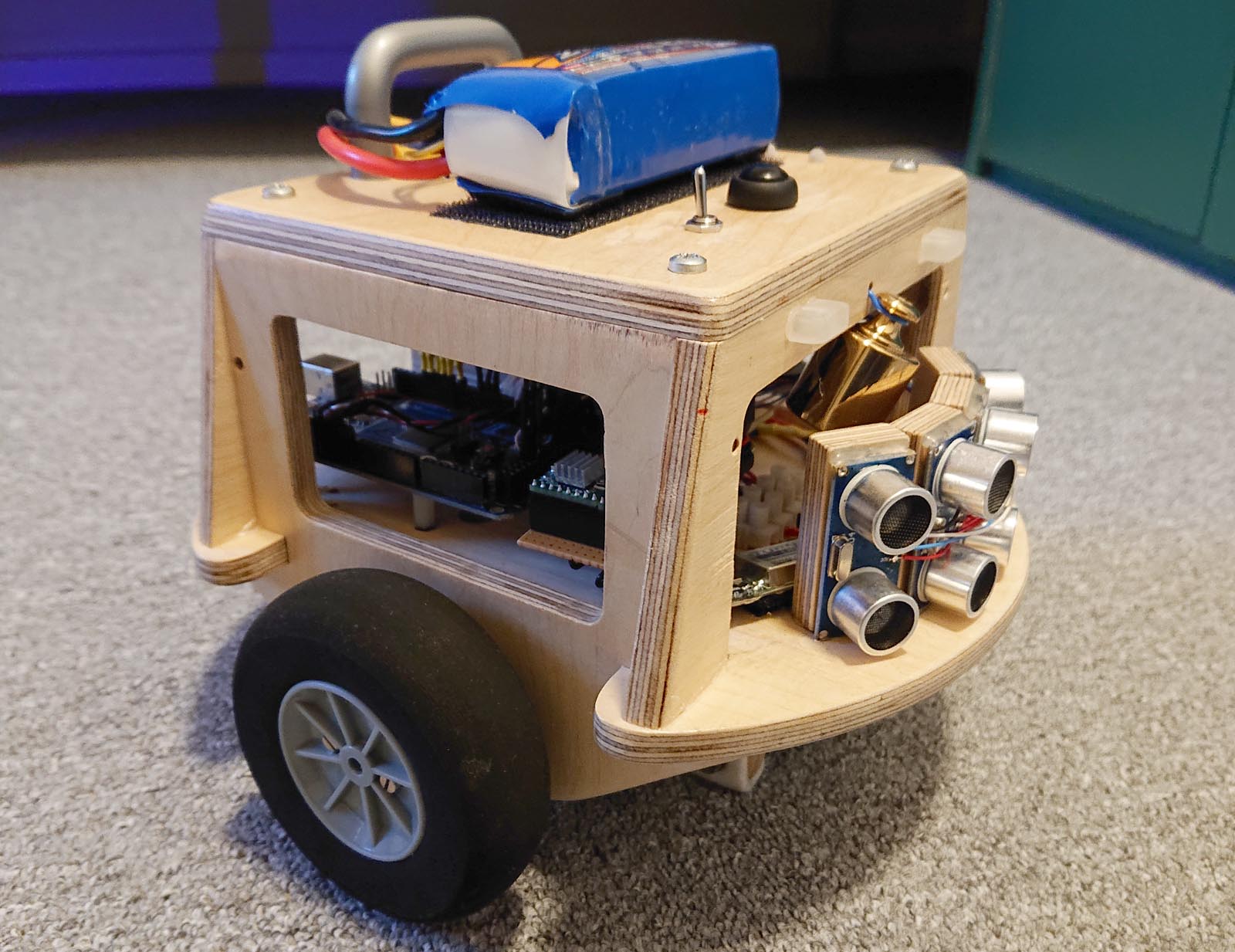
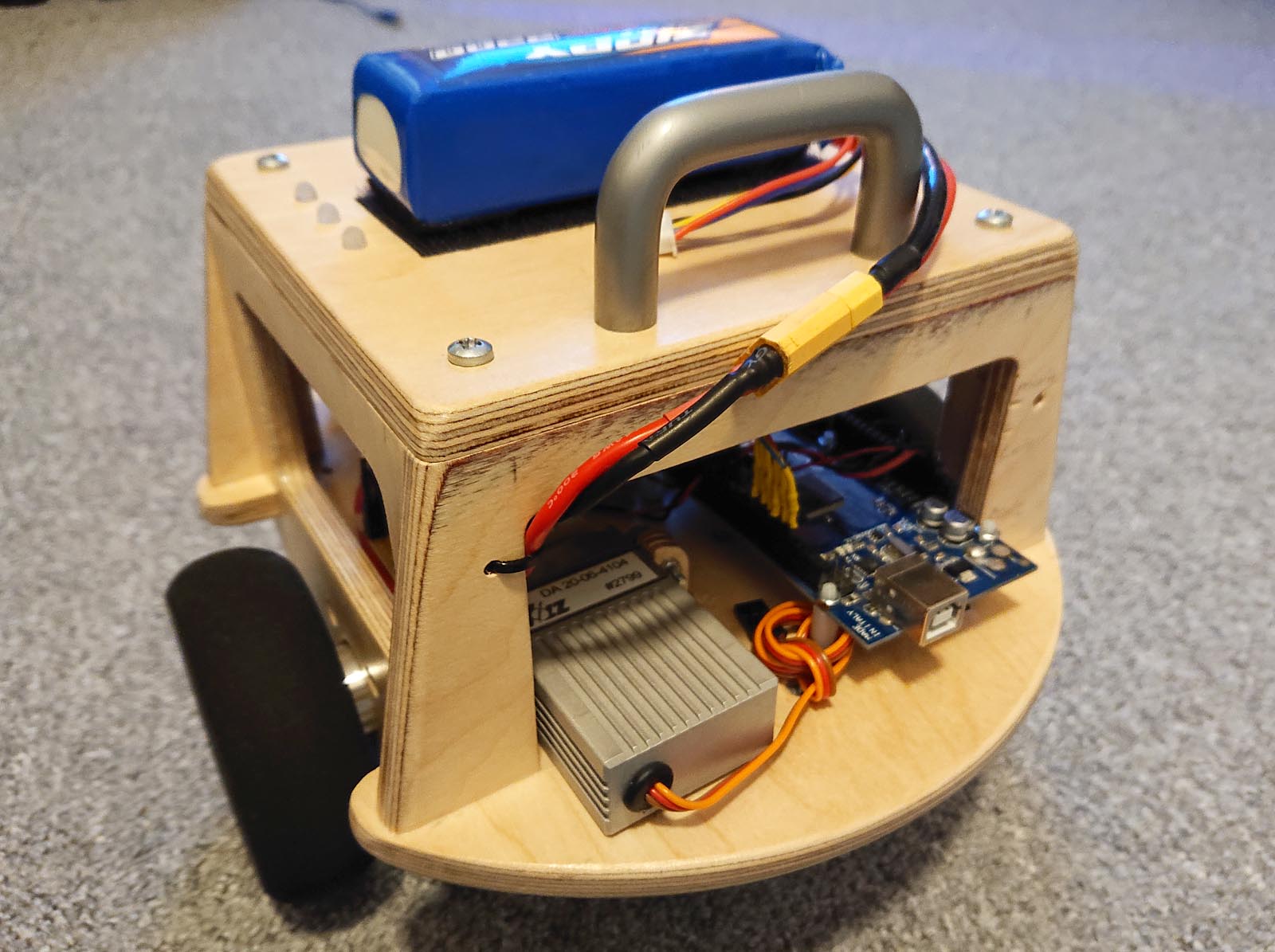
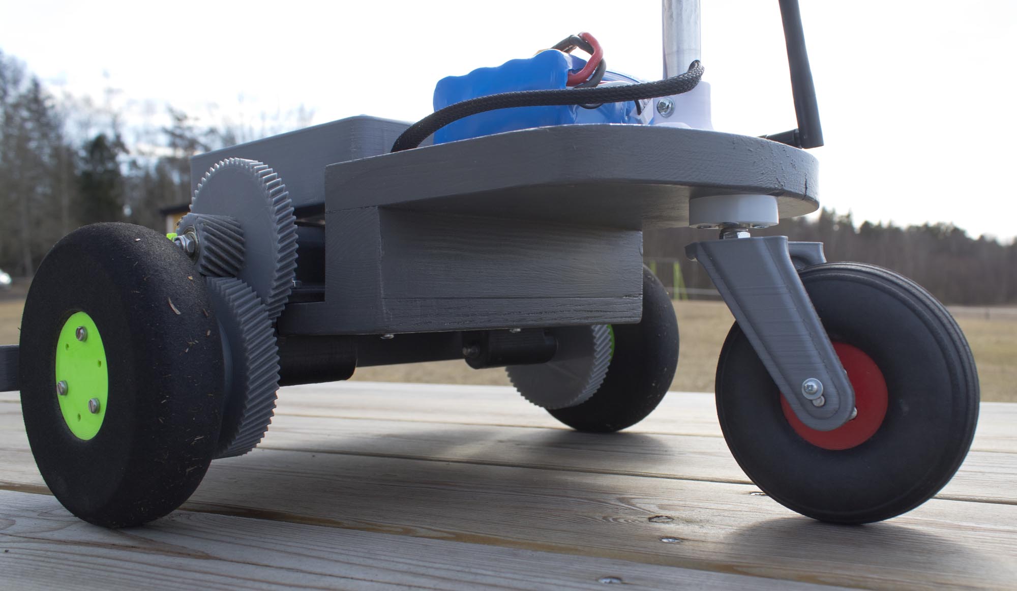
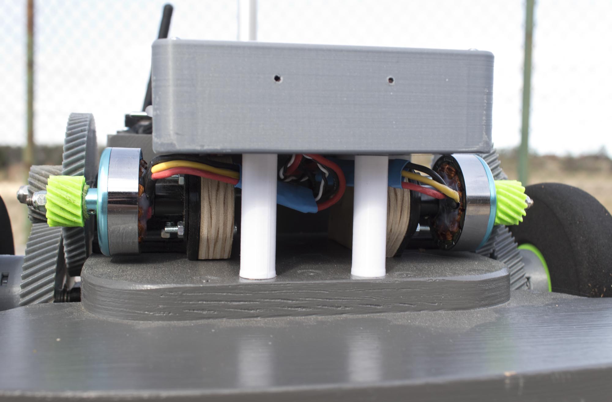
I built a robot running the ArduRover firmware. It has a differential drive system with two brushless sensorless drone motors and 3D printed gears. The video above is an overview of the robot and what it can do. The robot is built entirely to out parts I had laying around. The chassis is made out of wood and painted to make it look a bit better.
My intention was to use this robot as a base for adding sensors and other stuff and experiment with some of the features in ArduPilot/ArduRover. I later realized that I can’t do much more since this flight controller only has 1 MB or flash. Maybe I will change the flight controller in the future, or make another rover.
So far the robot has driven a total distance of about 15 km and the 3D printed gears still work well with almost no visible wear. They are printed out of standard PLA plastic.

Balancing robot part 3 – Remote control
I made a new version of the mainboard in the balancing robot, fixing all the problems with the previous one. I also got the prototype of the remote controller working. It is sending the X and Y values of the control stick to the robot. The robot is then adjusting its speed setpoint and turning variable based on those values.
The RC input probably needs some filtering. Now I just use the values directly, and if the user does to fast movements there is a risk that the robot falls over.
I am not satisfied with the remote yet. The biggest problem is the controls sticks I chose to use. They are really bad since only a small part around the center of each axis can be used as shown in the video. This makes it hard to control the robot with precision. I will probably redesign the remote to use a real control stick from an RC controller instead.
I have also planned to make the user interface on the remote for adjusting PID values and other parameters in the robot. This is the main reason why it has a display. More about that in a future video.
I have also installed two ultrasonic rangefinder sensors. They will be used for obstacle avoidance in the future, but I will finish the remote controller first.
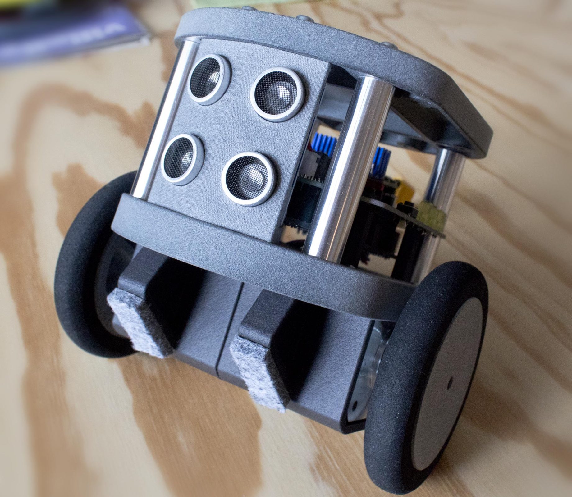

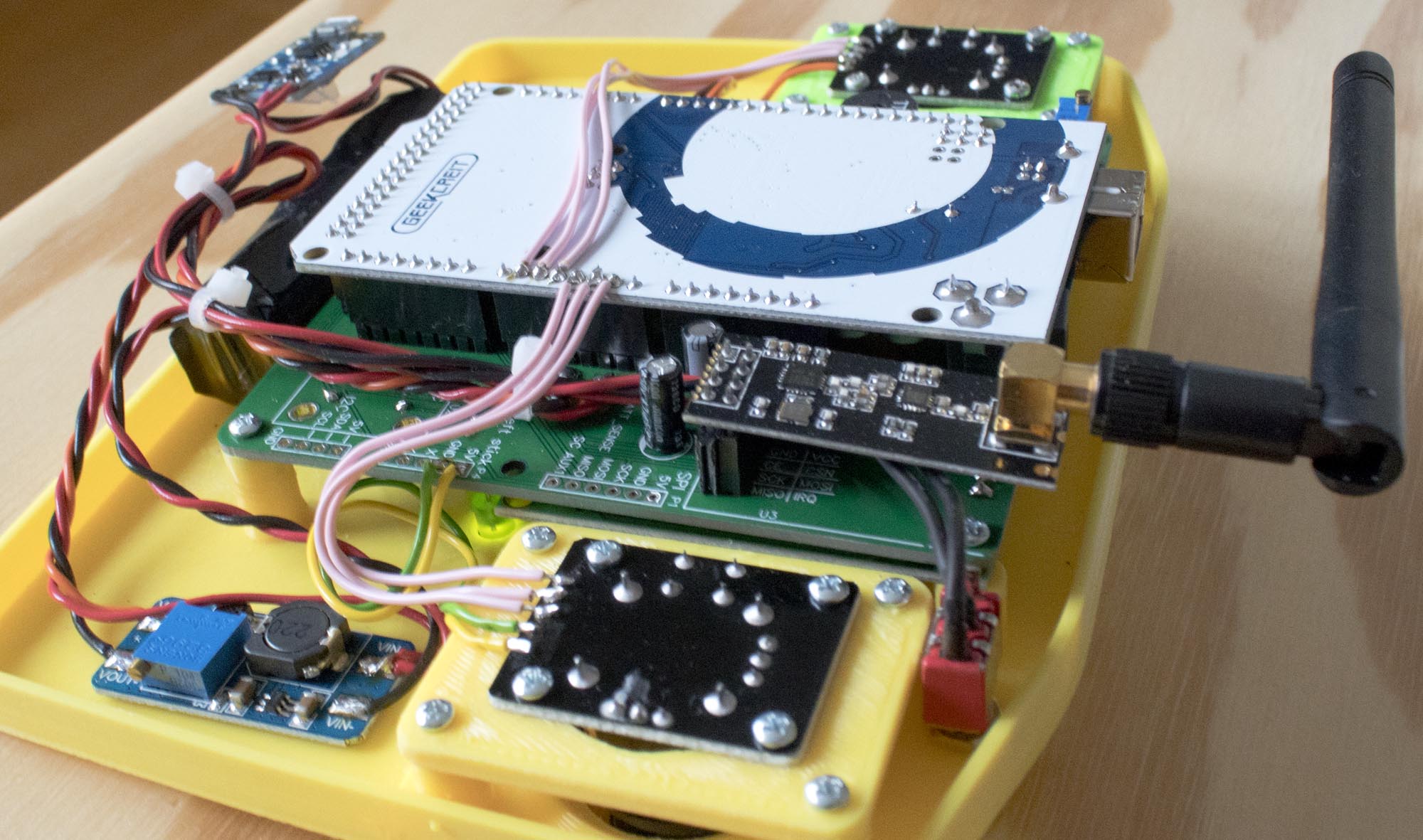
Prototyping and testing of the balancing robot
Made some progress on the balancing robot project. In this video, I made the first version of the PCB. It had a few problems but I still got the robot to balance. Some of the problems included:
- Design error with the voltage divider and filter capacitor for the battery voltage measuring. Capacitor blew up 🙂
- I forgot to connect the MISO, MOSI and SCK lines for the SPI bus.
- Problem with the fotprint for the wireless module.
- And a few more minior things…
Apparently, I need to check everything more carefully. Especially with the schematic, before I start to design the PCB itself. I hade also learned from many previous PCB projects that I have made, including this one, that you always need to create important/special component footprints yourself. Comunity-made footprints always have some errors, or something just decisions that I don’t like/want. Enev official footprints for components can have major problems.
In this video, I also show some of my planning of the remote controller for this robot. It will be a custom remote controller with an LCD and two analog control sticks. The controller should be able to control the robot, maybe in different ways. It will also have some kind of menu system for making adjustments to PID values and other settings.
A new self balancing robot
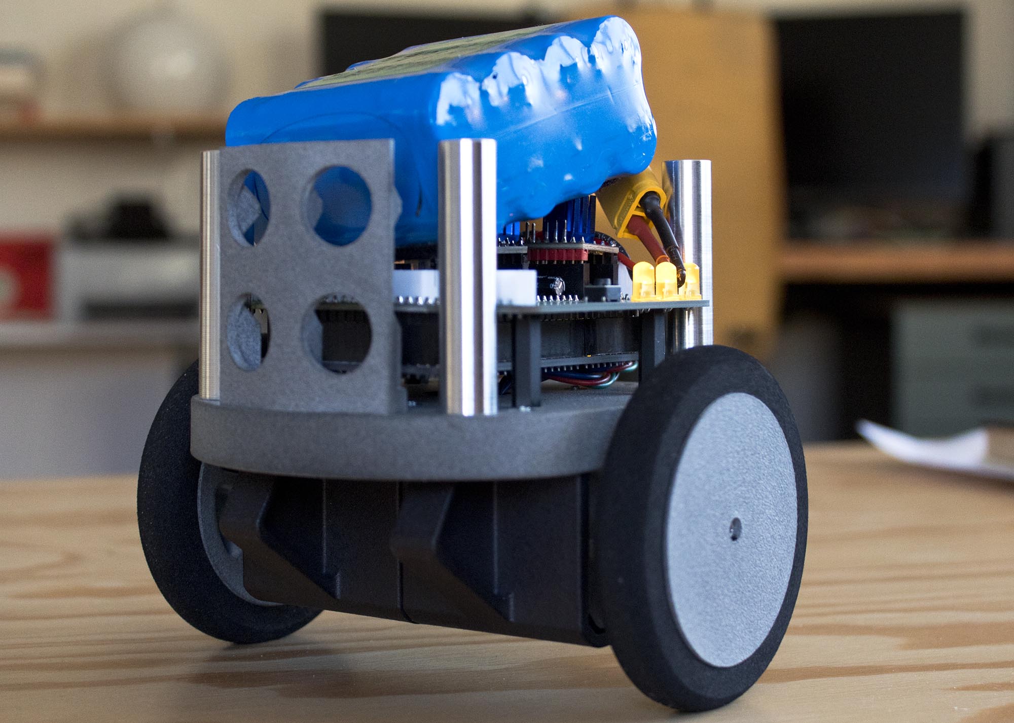
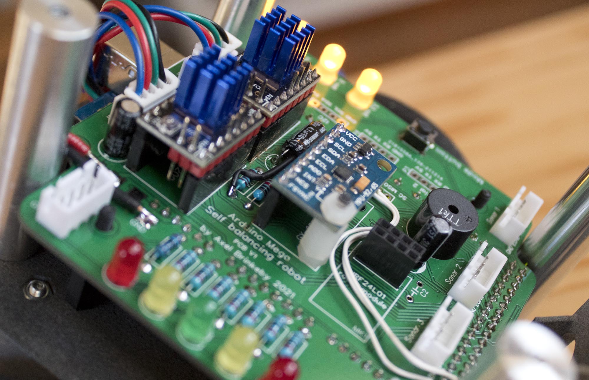
I started a new two-wheeled self-balancing robot project. I have built a few balancing robots before. This time, I want to make it even better. Trying out some new things while also making the robot even better documented and easier to replicate.
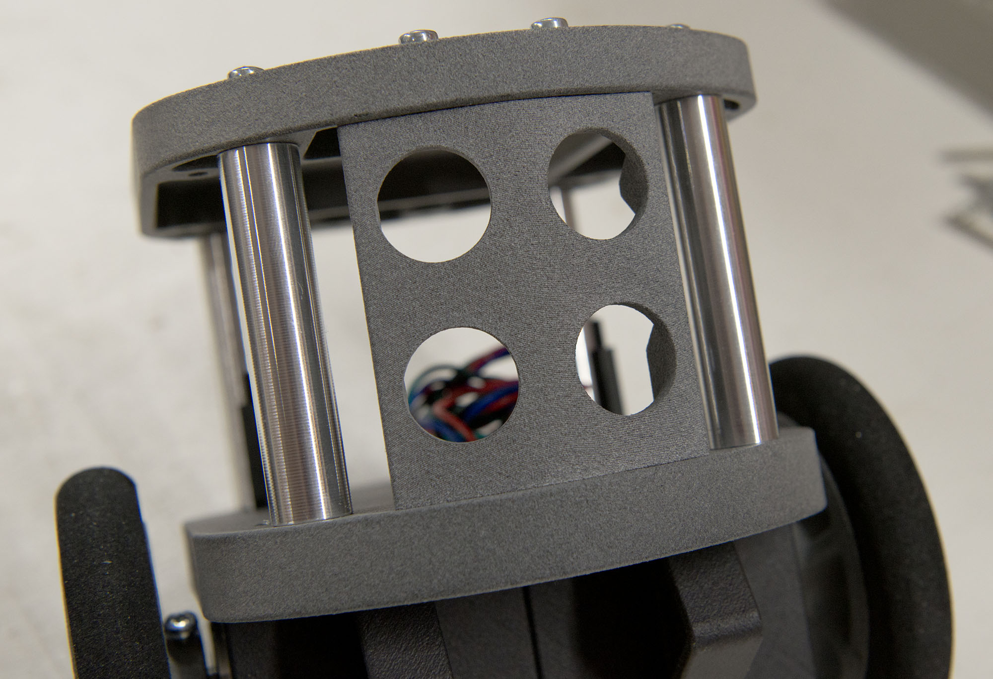
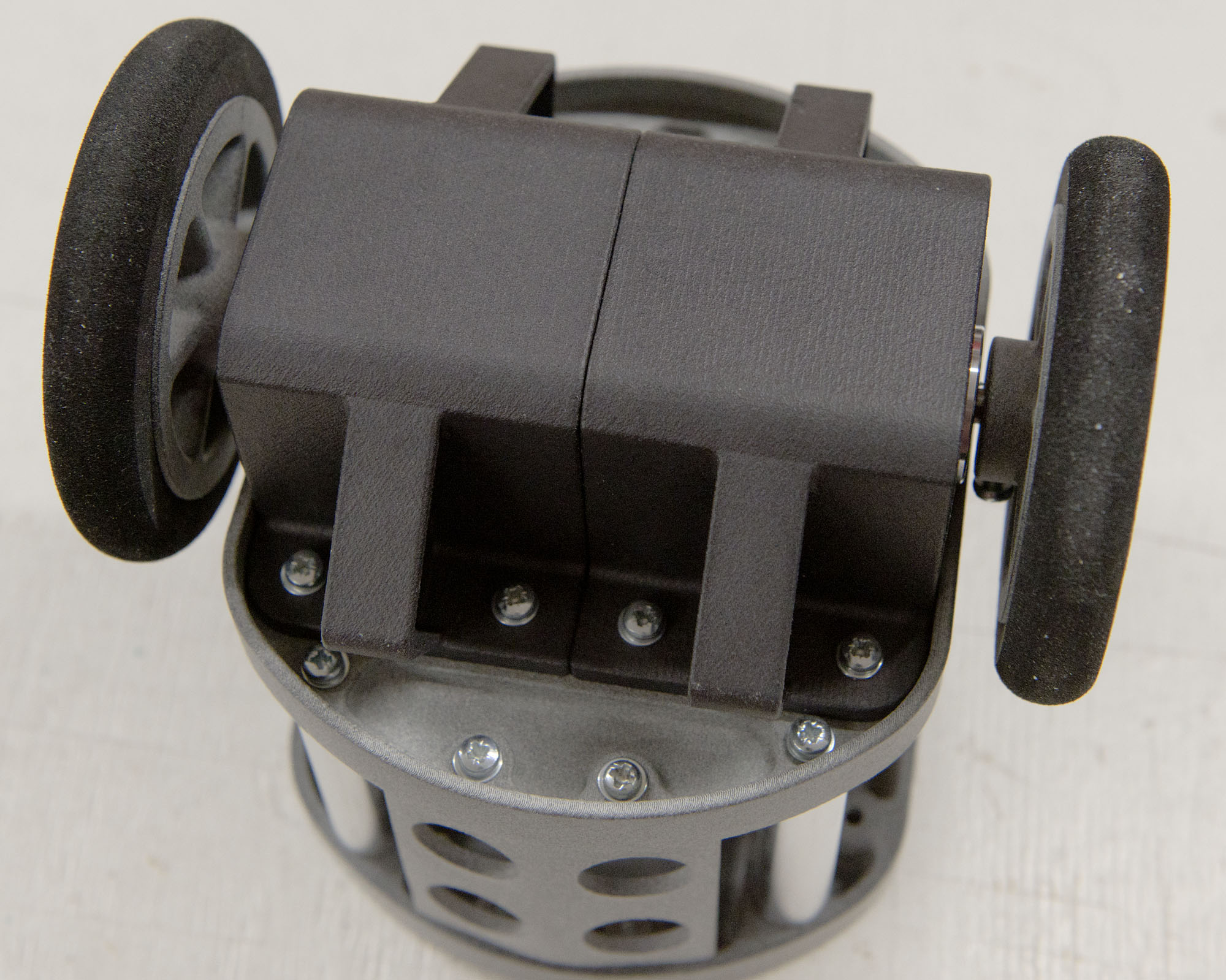
In this video, I make the chassis using 3D printed parts. The parts were sponsored by JLCPCB who 3D printed them for me. The parts are made out of PA-12 Nylon using MFJ 3D printing process. But those parts can also be printed using any standard filament printer you may have at home.
In later videos, I will make a PCB and show how I code and tune the robot. The robot will be remote-controlled, and also have an autonomous obstacle avoidance mode.
Here is a link to the 3D CAD files (Fustion360 files and STL files for 3D printing): http://brinkeby.se/downloads/2021%20Balancing%20Robot%203D%20CAD%20files.zip
The soft foam tires used are from RC plane wheels. I got them from this Swedish RC hobby shop: https://www.mbs-rcmodels.se/hjul/lattviktshjul-76mm-11g-2-pack/ I don’t think they ship outside of Sweden, or maybe they do. Maybe it is possible to find other tires that fit. I have also included STL files for the tires in the downloads if you want to try and print them out of TPU or similar.
Lidar Robot
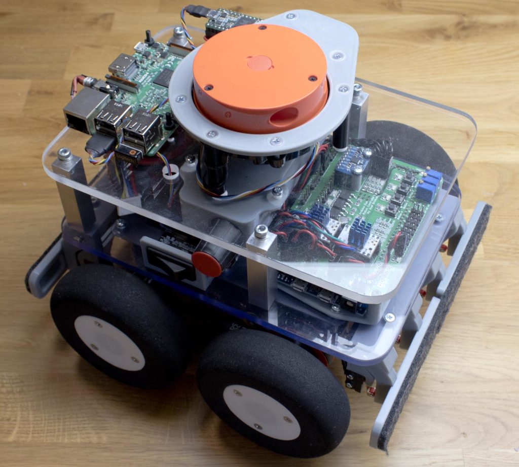
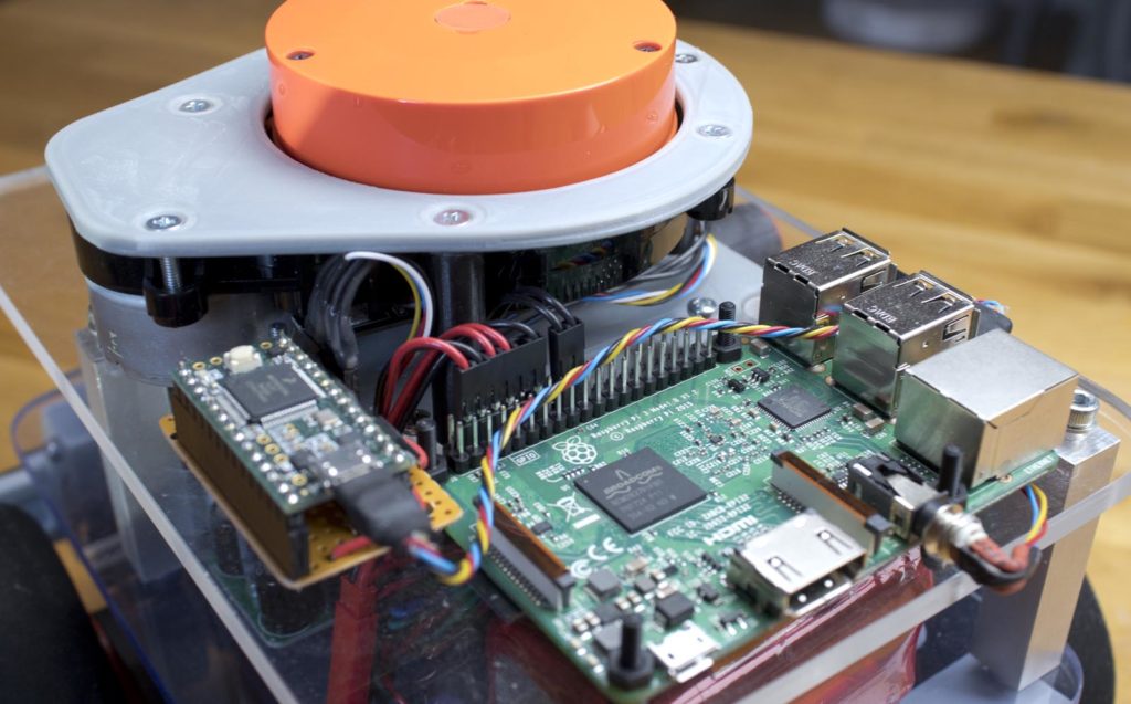
This is a video of my DIY Lidar robot. Here it is using a spinning laser distance sensor (Xiaomi robot vacuum spare part) to drive around and avoid obstacles. The sensor is connected to a Raspberry Pi running a Python script that is the main behavior program. There is no mapping going on, the robot is just going forward and turning away from things that are to close. The Raspberry Pi then sends serial data to an Arduino that controls stepper motors driving the robot.
The Xiaomi laser distance sensor is connected to a Teensy 3.2 running code from this project: https://github.com/getSurreal/XV_Lidar_Controller
The Teensy 3.2 is running PID speed control for the DC motor that spins the sensor. It is also reading the binary sensor data and sends it in easy to understand ASCII-messages over serial to the Raspberry Pi. The sensor spins at 5 revolutions per second and makes a distance measurement for every degree. Resulting in 360*5 = 1800 measurements per second. The accuracy is within a few centimeters. This sensor trigonometry to measure distance, in that way it is not a real Lidar sensor.
Arduino Mega Balancing Robot
I have re-built my old balancing robot using a single Arduino Mega instead of my previous solution using three different Arduinos. A better more optimized solution. Schematic and source code is available on the robot page here: https://axelsdiy.brinkeby.se/?page_id=1845

Rebuild of my “original” balancing robot.
This is the first self-balancing robot that I built that actually worked well. More info about it here. My absolute first self-balancing robot was the “Equaipose bot”, link the page about it here.
This video has gained some attention on youtube, and I think that is why I get at least one email every other week from people asking about the code and schematics for this robot. I have not shared the code of any details about this robot since it is very poorly made and coded. The robot uses multiple Arduinos just to keep the balance and drive the motors, later I also added another Arduino to manage the Ultrasonic sensors and some other stuff. There was also a Raspberry Pi that I planned to use for computer vision experiments, I never came around to doing that using this robot.
Now when I know a lot more about self-balancing robots, and Arduino programming and DIY robots in general, I decided to make a new version of this robot. I new complete rebuild of it. My intention is to make the robot less complicated and also better. I stripped down almost everything in the robot and started over. Still using the same old wooden chassis. The new version is based on a single Arduino MEGA R3 controlling everything in the robot. It reads the MPU6050 IMU, makes all the filtering and balancing calculations, and drives the motors using hardware timers for maximum precision. The new code for this robot is heavily based on the code for my “mini balancing robot”, with some improvements, more info about that robot here. I still use the same old stepper motors, model airplane wheels, and “Big Easy Driver” -stepper motor driver boards. The Arduino MEGA also controls and reads four HC-SR04 ultrasonic sensors using Interrupts. Those sensors are used for obstacle avoidance.
The new version of the robot works now. It balances and drives around avoiding obstacles, but I still have a few things to fix with the code. I want to add a pushbutton for control and a buzzer for feedback, I should also add battery measuring and implement a low voltage cut off to prevent damage to the battery.
I hope to release I video of the robot together with the code and schematic in a couple of weeks.
The servo seen in the pictures is not and will not be implemented in the first version of the code, but the intention is that the servo should be used to make it possible for the robot to raise itself up and start balancing on its own. Maybe I will also ad some sort of remote control since it is a frequently requested feature, But that will be in a later version.
Indoor navigation robot update
It has been some time since a worked on this robot. This is a video of me building and installing the main PCB on the robot. The video was actually recorded several months ago, but now I recently found the inspiration to continue to work on this project.
The main board has an Arduino Due that controls the two stepper motors that drive the wheels. The PCB also has a lot of other features including servo outputs/inputs, MOSFET outputs, bumper sensor inputs, 6 DOF IMU (gyro and accelerometer), a few buttons and LEDs, and a couple of other things. In the video, I connect an RC receiver the servo inputs on the board and drive the robot abound using remote control.
The future plans for this robot are to implement a serial interface in the Arduino Due, and then connect it the Rasberry Pi. That way the Rasberry Pi will be able the drive the stepper motors and also read data from the IMU and other sensors. Then I can make a python script or something running on the Pi that gives the robot some interesting behaviors.
I also plan a replacing the Time Of Flight LIDAR sensor mounted on the stepper motor seen in the video with a rotating Laser sensor instead. The problem with the Time Of Flight sensor is that it has a very limited range and sampling time. I recently found out about the rotating Laser Distance Sensor (LDS) used on Xiaomi robot vacuum cleaner robots. It is available for cheap as a replacement part the vacuum robots. There is also an open source project to control the spinning of the sensor an read data from it, which should make it relatively easy to connect to the Rasberry Pi in my robot.
GPS navigation robot – Two waypoints
This video shows a robot I have built that is driving between two waypoints using GPS.
I built this robot last summer, about a year ago. Back then, I never really managed to the software part of the robot working. The weather became worse outside as the fall came, and a lost interest in this project and started working on other things instead.
I wave written all the code myself, apart from the functions used to calculate course and distance between GPS waypoints. I used functions from the TinyGPS library for that. The code runs on an Arduino Due, the robot is using PID control to steer towards the waypoints. The robot uses a combination of GPS-course and integrating the signal from a yaw-gyro to determine its current course. The robot also has a compass, but it does not seem to work very reliably, therefore I do not use it. The robot also has sonar and other sensors, but they are not used in this video. Expect more videos and info about this robot in the near future.
